Tuesday, June 6, 2017

FreeRTOS 9.0.0 - Semaphores and Mutexes

Ok, so we now know what tasks notifications is all about. We know it can be used to pass simple messages, to make a task unblock or can be used as simple binary semaphore. Let's start with the semaphores. What are they? What do they eat? How do they multiply?

Binary semaphores

Let's start with the simplest of them, the binary semaphores. You can think of it as a totem, and only the person who has the totem can do something. Also this person is responsible of giving it back after one is done using it, and the totem will be given to the next person. 

Think of a family with 3 people at lunch time with only one microwave. Dad puts its dish to heat while mom and son are waiting for their turn. Mom asks to use it and then the son. Dad's turn is over and the mom starts heating her dish while the son starts complaining, hungry, but dad, who is late for work, just realised his dish is not hot enough and will need to use the microwave again. Mom's dish is heated and she goes to eat it while the son heats his dish and dad complains that he has to wait, because he's late, etc. Son leaves the microwave for dad and goes to eat. He heats his dish again and finally goes to eat too.

We had 3 people (tasks) with different priorities (dad late to work) and only one microwave (resource), thus only one person (task) could use the microwave (resource) at a time and the next person (task) can only use the microwave (resource) when the first person (task) releases it. Basically a FIFO, ignoring the tasks priorities.

A binary semaphore works in a similar way. Several tasks can ask for it ("take") and block (or not) while waiting, but only one task can have it at each time. When the task is done with it, it can either give it back ("Give") or just wait until someone else release the resource again. For the first scenario, you could think of the microwave example, where each task gives back the right to use the resource after it is done with it. A more comprehensive example could be a hardware with several components, all communicating through the same I2C peripheral, and one task responsible to communicate with each component. The communication is comprised of sending commands and receiving answers, so while each task is communicating with its component, no other tasks are allowed to use the I2C comm, until the first task frees the resource. For the second scenario, imagine a not frequent interruption (someone pressing a button): the interruption handler will give one binary semaphore at each key press, for which the task responsible to interpret the action will take it and do whatever it must do and then go to sleep, waiting for the next interruption to give another semaphore.

Care must be taken, though, that the binary semaphores don't allow being given more than once. In case you have an interruption that is too often, thus may occur more than once while the task which takes it is still processing, another mechanism should be used (counting semaphores, for example).

Finally, of course you could relate the binary semaphore to a queue with only one position, in which the value stored doesn't matter, but the fact that the queue is full or empty.

The API functions available for creating a binary semaphore are those below (it is created "empty", which means someone should give it for the first time). Giving or taking uses the same functions for other kinds of semaphores or mutex.

/* Creates a binary semaphore, allocated in the heap
Return: the handle for the semaphore or NULL (error) */
SemaphoreHandle_t xSemaphoreCreateBinary( void );

/* Creates a binary semaphore, allocated somewhere in RAM, according to pxSemaphoreBuffer
Returns: the handle for the semaphore or NULL if pxSemaphoreBuffer is NULL */ 
SemaphoreHandle_t xSemaphoreCreateBinaryStatic( StaticSemaphore_t *pxSemaphoreBuffer );

Counting Semaphores

Imagine you the family realized how much time they were wasting while waiting for the microwave to be used and decided to buy another microwave, exactly the same model. Now two people could heat their dishes at the same time!

Counting semaphores are commonly used to manage the use of resources, where the counting value represents the number of free resources. To obtain access to it, a task must successfully take the semaphore, which will decrement the counting value, and then give it back, which will increment it again. Another use of counting semaphores is counting event, when an event handler (interrupt handler, for instance) will give a semaphore every time the event occurs and the task that will process the event takes the semaphore. The counting value would be the difference between the amount of events that occurred and the amount of processed ones, or just the amount of event yet to be processed.

You can relate the counting semaphore to a queue with a length higher than one, where the value stored in each position isn't important, but the amount of data still in the queue.

The API for creating the counting semaphores and getting the count value is as follows. Once again, the take and give API is the same for the other kinds of semaphores and mutex and will be presented later.

/* Creates a counting semaphore, allowing to specify until how many it can count and the initial
count value, allocated in the heap
Returns: the handle for the semaphore or NULL (error) */
SemaphoreHandle_t xSemaphoreCreateCounting( UBaseType_t uxMaxCount,
                                            UBaseType_t uxInitialCount );

/* Similar to xSemaphoreCreateCounting, but the semaphore is stored somewhere in RAM, according 
to pxSemaphoreBuffer
Returns: the handle for the semaphore or NULL if pxSemaphoreBuffer is NULL */
SemaphoreHandle_t xSemaphoreCreateCountingStatic( UBaseType_t uxMaxCount,
                                                  UBaseType_t uxInitialCount,
                                                  StaticSemaphore_t *pxSemaphoreBuffer );

/* Returns the count value of the specified semaphore */
UBaseType_t uxSemaphoreGetCount( SemaphoreHandle_t xSemaphore );

Mutex

Mutex is a special case of binary semaphores, in the sense that it only has one position available for the resource to be used. The main difference is that now priority matters, which makes it a better choice for simple MUTual EXclusion cases, while the semaphores are better for task synchronisation. In my microwave example, if the family were using Mutexes instead of a binary semaphore, dad would reheat his dish before the son could heat his. Another difference from binary semaphores is that it can't be used inside interruptions.

One important thing is that with Mutexes, the task that took it must give it back. This is specially important when you have two tasks and both use the same two mutexes. Imagine task 1 takes mutex 1 and while it is processing, task 2 takes mutex 2. In order to task 1 finish whatever it is doing, it needs to take mutex 2 before giving mutex 1. In order to task 2 to finish, it needs mutex 1. This is a common design problem called deadlock. Each task is waiting the other to give the mutex and will never come to an agreement (unless the programmer implements some kind of protection). There are a few ways of preventing that:

  • Don't allow a task to take two mutexes at once
  • Using the timeout occurrence to prevent the task to be blocked forever
  • Don't share resources at all
  • Using a "Gatekeeper" to manage the access to the resource (basically a "manager" of the resource, so instead of taking the mutex, the tasks would use the services provided by the gatekeeper)
Regarding the priority inheritance in Mutexes, the objective is to make higher priority task wait as little as possible. This is how it works WITHOUT priority inheritance (with a binary semaphore, for instance): imagine a task 1 with priority 1 (low) took a mutex and is executing. During that time, task 2 with priority 10 (high) pauses task 1 execution, since it has a higher priority, and blocks while trying to take the mutex, which resumes task 1. Now task 3 with priority 5 (medium) pauses task 1 execution to do whatever it wants and after a while, blocks, what makes task 1 resume again. Task 1 finally gives the mutex and task 2 finally takes it and resumes its execution. What happened is that task 2 had to wait task 3 to execute, even though its priority is higher. This is called Priority Inversion, since a lower priority task managed to execute before a higher priority task.

To avoid that, FreeRTOS implements a priority inheritance mechanism. This means that when a higher priority task tries to take an already taken mutex, the lower priority task holding it momentarily gets its priority raised to the same priority of the other task. This means when task 2 tries to take the mutex, the mechanism raises task 1 priority to 10, avoiding any interrupts by task 3, which has priority 5 and executing as fast as possible in order to give the mutex and resume task 2. When the mutex is given, the original priority is restored, task 2 executes until for any reason it blocks again and only then task 3 will execute. It is important to remember that this mechanism doesn't prevent the priority inversion, since it has actually already happened (all in all, task 2 is still waiting for a lower priority task to execute), but rather minimises this problem. The ideal scenery would be one where the inversion never occurs in first place.

The API for creating a Mutex and getting the handle to the task holding the mutex. Once again, the take and give API is the same for the other kinds of semaphores and will be presented later.

/* Creates a Mutex stored in the heap
Returns: a handle to the mutex or NULL if out of memory */
SemaphoreHandle_t xSemaphoreCreateMutex( void );

/* Creates a Mutex stored somewhere in RAM, according to pxMutexBuffer
Returns: a handle to the mutex or NULL if pxMutexBuffer is NULL */
SemaphoreHandle_t xSemaphoreCreateMutexStatic( StaticSemaphore_t *pxMutexBuffer );

/* Gets the handle to the task holding the specified mutex
Returns: the handle to the task or NULL if no task holds it or xMutex is not a mutex */
TaskHandle_t xSemaphoreGetMutexHolder( SemaphoreHandle_t xMutex );

Just a small concern regarding the function xSemaphoreGetMutexHolder(): it can only reliably determine if the task calling the function is the mutex holder, since the holder can change between calling the function and getting its return value.

Taking and giving semaphores and common mutexes use the same API function which will be described below. Just remember Mutexes can't be used in interruptions, thus the functions ending in FromISR don't apply

/* Gives a binary semaphore or mutex or increments the count in a counting semaphore
Returns pdPASS if successful or pdFAIL if the task calling the function is not the holder */
BaseType_t xSemaphoreGive( SemaphoreHandle_t xSemaphore );

/* Same as before, but to be used in an interrupt (doesn't apply to mutex)
Parameter pxHigherPriorityTaskWoken is optional, but important: it will receive pdTRUE if a task
with higher priority than the interrupted was unblocked and a manual context switch is required
Returns pdTRUE if successful, or errQUEUE_FULL if a semaphore is already available (max count
in counting semaphores reached) */
BaseType_t xSemaphoreGiveFromISR( SemaphoreHandle_t xSemaphore,
                                  BaseType_t *pxHigherPriorityTaskWoken );

/* Takes a binary semaphore or mutex or decrements the count in a counting semaphore
Returns pdPASS if successful or pdFAIL otherwise */
BaseType_t xSemaphoreTake( SemaphoreHandle_t xSemaphore, 
                           TickType_t xTicksToWait ); /* 0 will return the function immediatly and portMAX_DELAY will make the task wait indefinitely */

/* Same as before, but to be used in an interrupt (doesn't apply to mutex)
Parameter pxHigherPriorityTaskWoken is optional and quite unlikely to be necessary. Same logic
as before (xSemaphoreGiveFromISR) applies
Returns pdTRUE if successful or pdFAIL if there wasn't a semaphore/mutex to be taken */
BaseType_t xSemaphoreTakeFromISR( SemaphoreHandle_t xSemaphore,
                                  signed BaseType_t *pxHigherPriorityTaskWoken );

Recursive Mutex

This is a special case of Mutex with which the task that has taken the mutex can take it many more times. Beware that the mutex MUST be given the same amount of times before any other task can take it. Like non recursive Mutexes, this type also implements the priority inheritance, thus it can't be used inside an interruption.

Recursive mutexes are mainly used in recursive functions that require exclusive access to some resource, thus taking the mutex is part of the recursive function code, as must be giving back the mutex.

The API for Recursive Mutex is unique and its functions are not interchangeable with common mutexes.

/* Creates a Recursive Mutex stored in the heap
Returns: Handle for the Recursive mutex or NULL if there is not enough memory left */
SemaphoreHandle_t xSemaphoreCreateRecursiveMutex( void );

/* Creates a Recursive Mutex stored somewhere in RAM, according to pxMutexBuffer
Returns: a handle to the mutex or NULL if pxMutexBuffer is NULL */
SemaphoreHandle_t xSemaphoreCreateRecursiveMutex( StaticSemaphore_t pxMutexBuffer );

/* Gives a Recursive Mutex one time
Returns pdPASS if successful, or pdFAIL if the task calling it wasn't the holder */
BaseType_t xSemaphoreGiveRecursive( SemaphoreHandle_t xMutex );

/* Takes a Recursive Mutex one time
Returns pdPASS if successfully obtained, pdFAIL otherwise */
BaseType_t xSemaphoreTakeRecursive( SemaphoreHandle_t xMutex,
                                    TickType_t xTicksToWait ); /* 0 will return the function immediatly and portMAX_DELAY will make the task wait indefinitely */

Deleting a Semaphore/Counting Semaphore/Mutex/Recursive Mutex is quite straightforward and uses the same function in all cases.
/* Deletes a Semaphore, Counting Semaphore, Mutex or Recursive Mutex */
void vSemaphoreDelete( SemaphoreHandle_t xSemaphore );


Ok, this post is already too long. I'll leave the explanation of the demo application to the next one...


Friday, June 2, 2017

FreeRTOS 9.0.0 on ArduinoMEGA - Full Demo - Task Notifications

After the Demo Blinky and Demo AVR323 I'm feeling more confident in this port, so let's get serious. Let's make the Full Demo work!

I'll try to follow the same order I used to describe the Full Demo here and get each module to work properly. I'll also use all the files used in AVR323 Demo project to start the Full Demo. To do that, I duplicated the AVR323 project with a different name (FreeRTOS_ArduinoMEGA-Demo_Full) and copied a few source and header files from the FreeRTOS folder.
  • The whole Standard Demo Header files can be copied to the project folder "FreeRTOS_ArduinoMEGA-Demo_Full\FreeRTOS\Demo\Common\include" folder (there was only the partest.h header). 
  • The source files should be copied from the folder "FreeRTOS 9.0.0\FreeRTOS\Demo\Common\Minimal" to the project folder "FreeRTOS_ArduinoMEGA-Demo_Full\FreeRTOS\Demo\Common\Minimal", but not all of them. The list follows:
    • AbortDelay.c
    • BlockQ.c
    • blocktim.c
    • countsem.c
    • death.c
    • dynamic.c
    • EventGroupsDemo.c
    • flop.c
    • GenQTest.c
    • integer.c
    • IntSemTest.c
    • PollQ.c
    • QPeek.c
    • QueueOverwrite.c
    • QueueSet.c
    • QueueSetPolling.c
    • recmutex.c
    • semtest.c
    • TaskNotify.c
    • TimerDemo.c
  • You'll also need to add a few source files that implement the FreeRTOS. Add the following from the folder "FreeRTOSv9.0.0\FreeRTOS\Source" to you project folder "FreeRTOS_ArduinoMEGA-Demo_Full\FreeRTOS\Source" (there was only list.c, queue.c and tasks.c, which are the bare minimum):
    • croutine.c
    • event_groups.c
    • timers.c
  • For the Full Demo, we'll need to use some dynamic allocation, thus change your heap file to the heap_5.c to have the full experience.
Finally, before we start, I suggest you compile the project as it is (essencially the AVR323 project) and correct any problems that may appear. For me, there were two problems:
  • References missing: go to Project > Properties > C/C++ General > Paths and Symbols > Includes > GNU C, add the following workpace paths:
    • /FreeRTOS_ArduinoMEGA-Demo_Full
    • /FreeRTOS_ArduinoMEGA-Demo_Full/FreeRTOS/Source/portable/WinAVR/ATmega2560
    • /FreeRTOS_ArduinoMEGA-Demo_Full/FreeRTOS/Source/include
    • /FreeRTOS_ArduinoMEGA-Demo_Full/FreeRTOS/Demo/Common/include
  • Definitions missing: on FreeRTOSConfig.h:
/* Software timer related configs - Full Demo */
#define configTIMER_TASK_PRIORITY ( configMAX_PRIORITIES - 1 )
#define configTIMER_QUEUE_LENGTH 20

/* The following includes are used in Full DEMO */
#define INCLUDE_eTaskGetState   1

With everything compiling correctly, even though it doesn't do anything different, we can start implementing (or actually just using the implemented algorithms) the Full Demo functions.

Tasks Notifications


Task notification is used to either send simple messages to another specific task or to just unblock the other task. This API can be considered a "lightweight" one position queue (called mailbox), since it is faster and consumes less RAM. To understand how it is used, let's assume we have two tasks, one I'll call Producer and one Consumer. The Producer will send a notification to the Consumer using  xTaskNotify(),  xTaskNotifyGive(),  xTaskNotifyAndQuery() or its interrupt safe equivalents, and will remain blocked until the Consumer receives the notification through  xTaskNotifyWait(),  ulTaskNotifyTake() or some task calls xTaskNotifyStateClear() with the Producer's handle as parameter. If the Consumer was already waiting for a notification, it will be immediately unblocked.

The notification value is a 32-bit value that every task has and that is cleared (set to zero) when the task is created. When sending a notification, the Producer can change the Consumer's notification value, either by overwriting, setting one or more bits or by an increment. The notification can also not be changed, if desired.

A fast and basic reference for the functions related to this API follows. Firstly, the functions used by the Producer (the one who sends the notification).

/* Notify a task
Returns: pdFAIL only if eAction is eSetValueWithoutOverwrite and there was another notification waiting, otherwise, pdPASS */
BaseType_t xTaskNotify( TaskHandle_t xTaskToNotify,
                        uint32_t ulValue, /* Interpretation of this value depends on eAction */
                        eNotifyAction eAction );

/* Notify and increment notification value 
Returns: pdPASS, always */
BaseType_t xTaskNotifyGive( TaskHandle_t xTaskToNotify );

/* Notify and retrieve the previous value
Returns: pdFAIL only if eAction is eSetValueWithoutOverwrite and there was another notification waiting, otherwise, pdPASS */
BaseType_t xTaskNotifyAndQuery( TaskHandle_t xTaskToNotify,
                                uint32_t ulValue, /* Interpretation of this value depends on eAction */
                                eNotifyAction eAction,
                                uint32_t *pulPreviousNotifyValue ); /* Returns the previous notification value from the Consumer */

The eAction is an enumerated type and can take one of the following values:

  • eNoAction - ulValue is not used, the task is just notified;
  • eSetBits - ulValue represents the bits that will be set in the Consumer's notification value (bits not set won't be altered);
  • eIncrement - ulValue is not used, the Consumer's value is incremented by one;
  • eSetValueWithOverwrite - ulValue is written in the Consumer's value;
  • eSetValueWithoutOverwrite - ulValue is only written if no other Producer is waiting for the Consumer to be notified (there is not a notification pending).
Functions used by the Consumer (the one who receives a notification) or other tasks.

/* Waits for a notification and changes the notification value according to xClearCountOnExit
Returns: the notification value before it's altered*/
uint32_t ulTaskNotifyTake( BaseType_t xClearCountOnExit, /* if pdTRUE, the notification value is reset to 0; if pdFALSE, the value is decremented by 1 */
                           TickType_t xTicksToWait ); /* Can wait forever, if set to portMAX_DELAY */

/* Waits for a notification, allowing the notification value to be altered bit by bit
Returns: pdFALSE if timed out, pdTRUE otherwise */
BaseType_t xTaskNotifyWait( uint32_t ulBitsToClearOnEntry, /* Bits to clear in the notification value before the enters the block state waiting for a notification */
                            uint32_t ulBitsToClearOnExit, /* Bits to clear in the notification value after the notification is received and the value is saved */
                            uint32_t *pulNotificationValue, /* Notification value resultant from the notification, before alteration according to ulBitsToClearOnExit */
                            TickType_t xTicksToWait ); /* Can wait forever, if set to portMAX_DELAY */

/* Clears a pending notification, not altering the notification value
Returns: pdPASS if there was a notification pendinge, otherwise pdFAIL */
BaseType_t xTaskNotifyStateClear( TaskHandle_t xTask ); /* xTask can be either the handle of another task that may have a notification pending or NULL, which reflects the task that called the function */


Full Demo's Task Notify


OK, API explained, now let's check what's happening in the DEMO. Basically what it does is create a common task, which will receive the notifications, thus represent the Consumer (check prvNotifiedTask()), and two Producers, one from a software timer (check prvNotifyingTimer()) and one from an interruption (check xNotifyTaskFromISR()). The interruption used is Tick interruption, through the use of the vApplicationTickHook().

The Producer from the interruption will notify the Consumer every 50 ms each time using a different API (vTaskNotifyGiveFromISR(), xTaskNotifyFromISR() and xTaskNotifyAndQueryFromISR()), always incrementing the notification value by one, but will only do that after the Producer from the sotware timer is already running. The Producer from the software timer always notifies the Consumer using the xTaskNotifyGive() and its period varies from 10 to 90 ms.

The Consumer will first raise some single tasks tests (check prvSingleTaskTests()), even before it creates the software timer:

  • Tries to take a notification (xTaskNotifyWait()), even though none has or will be given, in order to check if the timeout works;
  • Gives a notification to itself (xTaskNotifyAndQuery() setting the notification value without overwriting) and takes (xTaskNotifyWait()) it, in order to check if it will be done ASAP, thus no timeout-ing;
  • Checks the no-overwrite function by giving two notifications to itself  with different notification values and eSetValueWithoutOverwrite (xTaskNotify()) - the second should fail - and then taking only once (xTaskNotifyWait()) - the notification value should be equal to the first one given;
  • Same as before, but using overwrite: uses eSetValueWithOverwrite and different values, the value taken should be equal to last given.
  • Checks whether giving a notification with no changes to the value works by using xTaskNotify() with eNoAction and a value for the notification
  • Checks increments on the notification value by giving notifications for a known number of times (xTaskNotify() with eIncrement), then taking once and comparing the values; it tries to take again to ensure there are no more notifications pending;
  • Checks whether each bit of the notification value can be set by setting one bit at a time while giving (xTaskNotify() with eSetBits) and taking (the notification value is cleared before it starts through a xTaskNotifyWait() with all bits set on bits to clear on entry and no timeout) - it should run 32 times, since the notification value is 32 bit wide;
  • Checks if bits will be cleared on the entry and not on the exit by trying to take a notification, even though none was given, using xTaskNotifyWait() with bit0 (0x01) as bits to clear on entry and bit1 (0x02) as bit to clear on exit - as no notification was given, the bits are only cleared on entry.
  • Checks if bits will be cleared on exit by giving one notification, taking once with bit1 (0x02) as bits to clear on exit and trying to take again just to save the previous value.
  • Checks if the previous value is correctly received while notifying a task using xTaskNotifyAndQuery();
  • Finally, takes all notifications that might still exist (shouldn't be any), gives one generic notification and tries to clear the state twice (xTaskNotifyStateClear()), the first time should succeed and the second shouldn't.
Now back to the Consumer: after the tests described, it creates the software timer Producer, which will liberate the interruption Producer, and both will create notifications by incrementing the notification value, which means the value will be the amount of notifications given. So the consumer loop will:
  • Restart the software timer with a random period;
  • Try to take one notification with another random timeout and not clearing the value;
  • Try to take another notification, but this time not blocking but also not clearing the value;
  • Takes another notification, with the same timeout as before, but this time clearing the value;
  • Every 50 cycles, it raises the priority of the Consumer, receives all notifications by blocking until there is one available and reseting the counter (notification value), and restores the original priority (it tests the path where the Consumer is notified from an ISR and becomes the highest priority ready state task, but the pxHigherPriorityTaskWoken parameter is NULL - which it is in the tick hook that sends notifications to this task);
  • Finally, a counter of cycles is incremented.
There is one more function used, which is the Check function (xAreTaskNotificationTasksStillRunning()), responsible to check whether this Task Notify algorithm is still running. This function is called from the "Check Task" (prvCheckTask()), which is responsible to call, every 2.5 seconds, all check functions from all algorithms and warn in case something is going wrong. In the case of this algorithm, the function checks if the current number of cycles from the Consumer is higher than the last time it checked and if the number of times a notification was given is roughly the same of the taken ones. In case something is wrong, pdFAIL is returned.

Check Task


The check task (prvCheckTask()) is declared in main.c and is initialized with a low priority. Because the original code was designed to run in Windows, there was no problems with using printf(). With ArduinoMEGA things are obviously different, so a few changes were made. Instead of printing on the terminal, one LED is used to signalize that some problem occurred. A string (a static char *pcStatusMessage declared in main.c) is still used to signalize which error occurred, but it is treated as an array of chars with a defined size (mainERRORSIZE) and the messages always have this size, they are defined in a special header file (error_messages.h) and they're always transferred to the string using memcpy. Maybe in the future I could dispatch those messages through the serial port. Maybe.


Have fun!

Thursday, April 27, 2017

Back to Work - Eclipse Neon.3, WinAVR and Windows 10

Well, long time no see!
After a few changes in my personal life, I haven't got much time to write here. Now that everything is settling, I'm coming back to our beloved FreeRTOS!
So the first thing I needed to do was to set up my computer with all the applications and tools to make this work again.

So, I followed one of the first posts I wrote (this one), I downloaded the necessary tools and installed all. One main difference by now: Eclipse is currently in Neon.3 release, but it had so far no differences from the one I started with (Mars).

One thing should be noted, though. I wrote all the last posts either using Linux (Ubuntu) or Windows 7 (don't judge me, I liked it) and now my laptop has a Windows 10 (and Ubuntu on a Virtual Machine). When compiling any projects win WinAVR, I got this weird error:
make: *** [src/blink.o] Error -1073741502
It seems this is a Windows related problem, since the last version of WinAVR was developed in 2010. There are at least two solutions around the interwebs. One of them is to migrate to Atmel AVR Toolchain (Atmel takes care of the avr-gcc compiler now and WinAVR is no longer updated). The other solution is to download and "install" a new msys-1.0.dll. The later seemed like a better (quicker) solution to me, so you just need to download it (here for the 64 bits OS from this website) and replace the one in your WinAVR folder, especifically in
WinAVR-20100110\utils\bin
After that, the build command works like a charm, as it was supposed be.

One more tip, when importing the projects from Github, you'll probably need to create a new "Programmer configuration" for AVRDude. Open any project properties and navigate to AVR -> AVRDude. Tab Programmer, click in New, on Programmer Configuration block, follow the advices on the original post (this one): Atmel STK500 Version 2.x Firmware, choose the right COM Port and baudrate (115200bps).

New setup, now with RGB Leds:


See you soon.

Thursday, August 11, 2016

FreeRTOS 9.0.0 on ArduinoMEGA - Demo AVR323

Before we move on to the Demo Full, I'll first implement the same Demo you can find for the AVR323 port ("FreeRTOSv9.0.0\FreeRTOS\Demo\AVR_ATMega323_WinAVR"). This way we can check closely on how to configure the serial port, which will be very helpful for debugging purposes when we move on to the Demo Full.

To quick start, grab the source code in https://github.com/brunolalb/FreeRTOS_ArduinoMEGA-Demo_AVR323

For that, first we'll need a few extra files from the FreeRTOS.

  • From the folder "FreeRTOSv9.0.0\FreeRTOS\Demo\Common\include", copy the following files to the project folder "FreeRTOS_ArduinoMEGA-Demo_AVR323\FreeRTOS\Demo\Common\include": 
    • integer.h,
    • comtest.h,
    • serial.h,
    • PollQ.h,
    • crflash.h
  • From the folder "FreeRTOSv9.0.0\FreeRTOS\Demo\Common\Minimal", copy the following files to the project folder "FreeRTOS_ArduinoMEGA-Demo_AVR323\FreeRTOS\Demo\Common\Minimal": 
    • integer.c,
    • comtest.c,
    • PollQ.c,
    • crflash.c
  • A few other source files will have to be created (or adapted from the existing ones), so copy the folder "FreeRTOSv9.0.0\FreeRTOS\Demo\AVR_ATMega323_WinAVR\serial" to your project's root (it has the implementation of the serial port routines). 
  • The registers test routine, present in the ATmega323 Demo project can also be used, so I created a "RegTest" folder in the root of my project and added the regtest.c and regtest.h available in "FreeRTOSv9.0.0\FreeRTOS\Demo\AVR_ATMega323_WinAVR". 
  • Finally, for the co-routine capability be present, the source file croutine.c, available in "FreeRTOSv9.0.0\FreeRTOS\Source" must be copied to your projects folder "FreeRTOS_ArduinoMEGA-Demo_AVR323\FreeRTOS\Source".


On the following paragraphs, I'll describe the changes I made in the AVR323 Demo to run in our ArduinoMEGA port.

serial.c

As I told before, the serial routines are implemented in this file and they're very platform dependent, as many internal registers will be manipulated. This file is located in your project folder (if you copied the files I told you to) "FreeRTOS_ArduinoMEGA-Demo_AVR323\serial\serial.c". I understand the ATmega2560 has 4 serial ports (serial 0 to 3), but right now, I'm only implementing the Serial0, which is the one available on the USB connection. In the future, the serial.c can be modified to implement all the 4 hardware UART.

Basically what is needed is to correct the registers and interrupt vector names to the right ones, according to the microcontroller's datasheet. Besides that, I'm also using the option to double the communication speed, which will reduce the baud rate error rate (see table 22-12, page 226 of the datasheet), specially when using 115200 bps. Also, to enhance the routines, I added some error detection to the reception interrupt by checking the UCSRnA register prior to reading the data.

main.c

This file had several changes. First of all, I wanted it to keep the Demo Blinky routines, as I knew they're already working and blinking its LED, so it would be a good way of knowing if the program halted for some reason. Also, my approach on merging both projects (Demo Blinky and Demo AVR323) was to add each task creation call and compile. It wouldn't work, of course, so I would go after the missing headers and source files and compile again until it worked. So I added a bunch of flags to enable or disable each functionality. In the end, I got everything to work almost out of the box. Almost, as I realized a few things:

  • The coroutines use the first 3 LEDs (LEDs 0, 1 and 2) and this isn't easily configurable, so I made them available in the ParTest.c.
  • The Demo Blinky was configured to blink the LED 3
  • The Communication Tests uses the configured LED (4, for reporting a TX) and the next one (5, for reporting a RX) and expect to receive the same value it sent (a loop connection)
  • The Error Check task was configured to blink the LED 6 while the program worked fine (it stops blinking if something goes wrong).
  • The Assert Called function kept its LED number 7.
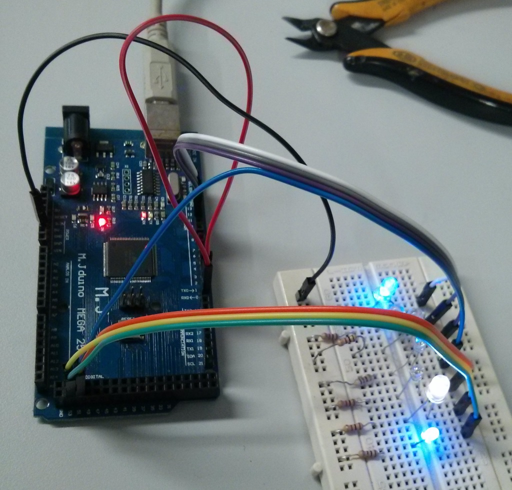
To see all that working, I had to place all LEDs in a protoboard, but don't forget to check Arduino's pin mapping to connect everything. The whole PORTB will blink LEDs now. The connection is as follows:

LED number Pin Name Mapped Pin Function
0
PB0
Digital 53
Co routine
1
PB1
Digital 52
Co routine
2
PB2
Digital 51
Co routine
3
PB3
Digital 50
Demo Blinky
4
PB4
Digital 10
Com Test - TX
5
PB5
Digital 11
Com Test - RX
6
PB6
Digital 12
Erro Check
7
PB7
Digital 13
(on board LED)
Assert Called


The project was uploaded to GitHub.

Tuesday, August 9, 2016

FreeRTOS 9.0.0 on ArduinoMEGA - Demo Blinky

By now, we have a <seemingly> operating FreeRTOS running in our ArduinoMEGA, but we're not using its whole capability. In order to test more functions, let's add a few functionalities step by step until we reach the Full Demo.

To quick start, grab the source code in https://github.com/brunolalb/FreeRTOS_ArduinoMEGA-Demo_Blinky.

FreeRTOS Demo Blinky

Yet another blinky project. This time I'm using the functionality we've studied a few months ago: here and here. This blinky project makes use of a Queue and has two tasks instead of one. One task (prvQueueSendTask()) is a sender and will add a constant value to a queue every 200 ms, while the other task (prvQueueReceiveTask()) is the receiver and will try to get the value from the queue (blocking operation) and, if the value is right, will toggle a LED on PORTB.PB6 (the same from the Blink project).

Another test performed in this project is the implementation of the configASSERT() function, which is very useful for debugging purposes. In this project, a parameter is passed to the tasks when they're created and the task should check it in order to attest that it's right. The configASSERT() will turn on the LED embedded in ArduinoMEGA's board (PORTB.PB7), as by now there's nothing much implemented yet. In the future, it could be changed to a message sent through the Serial port.

To get things moving faster, I thought on using the whole main_blinky.c from the Win32 Demo with as little changes as possible. The problem is that it wouldn't be very efficient, once the Windows Demo uses several long variables (32 bits wide) and we're running on an 8-bits microcontroller. Thus I made a few changes to optimize the code.

The main() function initializes not only the queue, which now stores unsigned char variables, but also the LEDs, using the same function as the Blink project. It then creates both tasks with predefined parameters (changed to accommodate one unsigned int) and starts the scheduler.

int main( void )
{
 /* Create the queue. */
 xQueue = xQueueCreate( mainQUEUE_LENGTH, sizeof( unsigned char ) );

 /* Setup the LED's for output. */
 vParTestInitialise();
 if( xQueue != NULL )
 {
  /* Start the two tasks as described in the comments at the top of this file. */
  xTaskCreate( prvQueueReceiveTask,   /* The function that implements the task. */
        "RX",      /* The text name assigned to the task - for debug only as it is not used by the kernel. */
        configMINIMAL_STACK_SIZE,    /* The size of the stack to allocate to the task. */
        ( void * ) mainQUEUE_RECEIVE_PARAMETER, /* The parameter passed to the task - just to check the functionality. */
        mainQUEUE_RECEIVE_TASK_PRIORITY,   /* The priority assigned to the task. */
        NULL );     /* The task handle is not required, so NULL is passed. */

  xTaskCreate( prvQueueSendTask, "TX", configMINIMAL_STACK_SIZE, ( void * ) mainQUEUE_SEND_PARAMETER, mainQUEUE_SEND_TASK_PRIORITY, NULL );
 }

 /* In this port, to use preemptive scheduler define configUSE_PREEMPTION
 as 1 in portmacro.h.  To use the cooperative scheduler define
 configUSE_PREEMPTION as 0. */
 vTaskStartScheduler();

 return 0;
}

The receiver task now blinks a LED instead of printing something. The request from the queue blocks the task for a long time while waiting something to be added to it.

static void prvQueueReceiveTask( void *pvParameters )
{
unsigned char ucReceivedValue;

 /* Remove compiler warning in the case that configASSERT() is not
 defined. */
 ( void ) pvParameters;

 /* Check the task parameter is as expected. */
 configASSERT( ( ( unsigned int ) pvParameters ) == mainQUEUE_RECEIVE_PARAMETER );

 for( ;; )
 {
  /* Wait until something arrives in the queue - this task will block
  indefinitely provided INCLUDE_vTaskSuspend is set to 1 in
  FreeRTOSConfig.h. */
  xQueueReceive( xQueue, &ucReceivedValue, portMAX_DELAY );

  /*  To get here something must have been received from the queue, but
  is it the expected value?  If it is, toggle the LED. */
  if( ucReceivedValue == 100UL )
  {
   /* The Windows Blinky Demo prints a message with printf().
    * In Arduino, we'll just blink a LED */
   vParTestToggleLED(mainLEDBLINK_TASK_LED);

   ucReceivedValue = 0U;
  }
 }
}

The sender task gave a bit more trouble, even though the changes in its code were minimal (this is why I'm not pasting it here). Its objective is to add a certain value to the queue, then sleep for a certain amount of time (200 ms). Instead of using the vTaskDelay(), as used in our last project, it uses the vTaskDelayUntil() (it is used to ensure the routine will run every X milliseconds, despite the execution time), and the time was previously defined in milliseconds. To calculate the number of ticks to wait, the pdMS_TO_TICKS() macro is used. If you expand the macro (you can check in FreeRTOS/Source/Include/projdefs.h), you'll see that it multiplies the time, in milliseconds, with the tick rate in Hz, casting everything to TickType_t, which, in Windows is an uint32_t (thus 32-bits), but in our port is an uint16_t (thus 16-bits). This means it will multiply 200 (ms) with 1000 (Hz), which exceeds 16-bits. In order to the macro to work, it has to be redefined in FreeRTOSConfig.h (if you check the comments in projdefs.h, it's already something expected). This is what was added to the end of the header:

/* It is a good idea to define configASSERT() while developing.  configASSERT()
uses the same semantics as the standard C assert() macro. */
extern void vAssertCalled( unsigned long ulLine, const char * const pcFileName );
#define configASSERT( x ) if( ( x ) == 0 ) vAssertCalled( __LINE__, __FILE__ )

/* Due to problems with integer overflow, this macro is defined here */
#define pdMS_TO_TICKS( xTimeInMs ) ( ( TickType_t ) ( ( ( unsigned long ) ( xTimeInMs ) * ( unsigned long ) configTICK_RATE_HZ ) / ( unsigned long ) 1000 ) )

As you can see, I casted this multiplication operation to an unsigned long, which is 4 bytes wide.

The vAssertCalled(), which is defined in main.c only sets the LED.

void vAssertCalled( unsigned long ulLine, const char * const pcFileName )
{
 /* Parameters are not used. */
 ( void ) ulLine;
 ( void ) pcFileName;

 vParTestSetLED(mainASSERTCALLED_LED, pdTRUE);
}

The project was uploaded to GitHub.

Friday, August 5, 2016

FreeRTOS 9.0.0 on ArduinoMEGA - Blink project

For a quick start, refer to the project on github:
http://github.com/brunolalb/FreeRTOS_ArduinoMEGA-Blink

FreeRTOS 8.2.3 to 9.0.0 changelog

It's finally time to start working on the FreeRTOS port to ArduinoMEGA. It's been a long time since I started this blog that even a new version of FreeRTOS came up. The system is now on 9.0.0 version, so that's the one I'll use from now on. So first of all, you should download the source code from their website: click here. There aren't many differences from the latest version and the code is pretty much compatible. The complete changelog can be checked here, but I'll describe some of the new features, enhancements and new ports implemented.

  • Support to completely statically allocated systems: remember the post about the memory allocation systems? heap_1.c, heap_2.c, etc? Those were about dynamic allocation. The new version supports static allocation, which means the RAM footprint is defined by linking time, rather than running time. More info can be found here and here.
  • Forcing a task to leave the blocked state: while the task is waiting for something (a semaphore take with timeout or a simple delay), the task is remained in blocked state. The new version implements an API function that unblocks a task (xTaskAbortDelay()). More info here.
  • Deleting tasks: in prior versions, when a task was deleted, its memory were only freed by the Idle function, independently of who has deleted it. Now, when one task is deleted by another task, the memory (stack and TCB) is freed immediately.
  • Obtaining a Task Handle from the Task Name: it's now possible to do this with the new API function: xTaskGetHandle(). More info here.
  • configAPPLICATION_ALLOCATED_HEAP: it's now possible to specify the memory position where the heap will be allocated when using heap_1 or heap_2 (and heap_4, but that was already possible) by declaring the array "uint8_t ucHeap[ configTOTAL_HEAP_SIZE ];". More info here.

Creating required files and the Eclipse project

The initial objective will be to have the bare minimal amount of code to run the FreeRTOS and just make a LED blink. On your file explorer, create the folder where your project will be. In that folder, create another folder called FreeRTOS, where we'll keep all the RTOS code, just for cleanliness purposes. Let's copy the source files from the FreeRTOS official folder:
  • The basic kernel: Source/tasks.c, queue.c and list.c
  • Memory management: Source/MemMang/heap_1.c (this is the simpler one)
  • The portable bits: Source/portable/[compiler]/[processor]/port.c and portmacro.c
    • In this case, I created the folder WinAVR as the [compiler] and ATmega2560 as the [processor].
    • I copied the files from the ATmega323 port (FreeRTOSv9.0.0\FreeRTOS\Source\portable\GCC\ATMega323) to start with something close to what I want.
  • Header files: Source/include/ (you may copy the whole folders) and Demo\Common\include\partest.h.
To the root folder of the project we'll add the application specifics (I copied them from the ATmega323 Demo project, in FreeRTOSv9.0.0\FreeRTOS\Demo\AVR_ATMega323_WinAVR):
  • FreeRTOSConfig.h 
  • main.c
  • ParTest/ParTest.c
This is what we have in our project folder:


Supposing that you already have your Eclipse configured (if not, check here), open it and go to File > New > C++ Project.
  1. Choose the Empty Project under the folder "AVR Cross Target Application"
  2. Pick a name (FreeRTOS_ArduinoMEGA - rev0.1) and point the location to your project folder


  3. Click Next
  4. Click Next again (Debug and Release configs)
  5. Choose the MCU (ATmega2560) and Frequency (16000000 - that's 16 followed by 6 zeroes, 16MHz)
  6. Click Finish. This is what your Project Explorer should be showing:


  7. In the Project Properties, under AVR > AVRDude, in the box Programmer Configuration, choose the config you created for the Blink project (or follow the steps 9 and 10 here): ArduinoMEGA2560 - STK500v2.
  8. Still on the Project Properties, go to C/C++ Build > Settings. On the tab Tool Settings:
    1. Additional Tools in Toolchain, check "Generate HEX file for Flash memory"
    2. AVR Compiler > Optimization, Optimization Levels: Size Optimization (-Os), uncheck Pack Structs and Short Enums
    3. AVR Compiler > Language Standard, uncheck "char is unsigned" and "bitfields are unsigned"
    4. Do the same to AVR C++ Compiler
  9. Adjusting some paths under C/C++ General > Paths and Symbols > Includes, add the following workspace directories:
    1. Project's root
    2. FreeRTOS/Demo/Common/include
    3. FreeRTOS/Source/include
    4. FreeRTOS/Source/portable/WinAVR/ATmega2560
By now, the project should be ready, but the code is all wrong, so let's work on that.

Working on port.c and portmacro.h

Before we start, we should define a few things. First of all, the main timer for the FreeRTOS (the one that will provide the Tick) will be Timer 1 and the Tick will be 1 ms (1000 Hz). No special reason, as it could be any other, but two things made me choose this: it's the same used in AVR323 and it's the same time we used on the Blink project.
This timer should produce interrupts every 1 ms, without any interference of the FreeRTOS functions, thus a simple timer that counts to a certain value, indicates an interrupt and resets on its own, restarting the process. Refer to the function prvSetupTimerInterrupt( void) around line 402 of the port.c file. There are a few differences, since the ATmega323 is bit simpler.
/*
 * Setup timer 1 compare match A to generate a tick interrupt.
 */
static void prvSetupTimerInterrupt( void )
{
uint32_t ulCompareMatch;
uint8_t ucHighByte, ucLowByte;

 /* Using 16bit timer 1 to generate the tick.  Correct fuses must be
 selected for the configCPU_CLOCK_HZ clock. */

 ulCompareMatch = configCPU_CLOCK_HZ / configTICK_RATE_HZ;

 /* We only have 16 bits so have to scale to get our required tick rate. */
 ulCompareMatch /= portCLOCK_PRESCALER;

 /* Adjust for correct value. */
 ulCompareMatch -= ( uint32_t ) 1;

 /* Setup compare match value for compare match A.  Interrupts are disabled 
 before this is called so we need not worry here. */
 ucLowByte = ( uint8_t ) ( ulCompareMatch & ( uint32_t ) 0xff );
 ulCompareMatch >>= 8;
 ucHighByte = ( uint8_t ) ( ulCompareMatch & ( uint32_t ) 0xff );
 OCR1AH = ucHighByte;
 OCR1AL = ucLowByte;

 /* Setup clock source and compare match behaviour. */
 ucLowByte = portCLEAR_COUNTER_ON_MATCH_TCCR1A;
 TCCR1A = ucLowByte;
 ucLowByte = portCLEAR_COUNTER_ON_MATCH_TCCR1B | portPRESCALE_64;
 TCCR1B = ucLowByte;

 /* Enable the interrupt - this is okay as interrupt are currently globally
 disabled. */
 ucLowByte = TIMSK1;
 ucLowByte |= portCOMPARE_MATCH_A_INTERRUPT_ENABLE;
 TIMSK1 = ucLowByte;
}
/*-----------------------------------------------------------*/
You probably realize two changes: The addition of the TCCR1A config and the correct config of the TIMSK1 register (was TIMSK on ATmega323). The definitions (around line 90) change to the following.
/* Hardware constants for timer 1. */
#define portCLEAR_COUNTER_ON_MATCH_TCCR1A  ( ( uint8_t ) 0b00000000 )
#define portCLEAR_COUNTER_ON_MATCH_TCCR1B  ( ( uint8_t ) 0b00001000 )
#define portPRESCALE_64     ( ( uint8_t ) 0b00000011 )
#define portCLOCK_PRESCALER    ( ( uint32_t ) 64 )
#define portCOMPARE_MATCH_A_INTERRUPT_ENABLE  ( ( uint8_t ) 0b00000010 )

Even though both microcontrollers use the same AVR architecture, the ATmega2560 has 2 more registers to be saved: RAMPZ and EIND, thus the functions portSAVE_CONTEXT() and portRESTORE_CONTEXT() will need a tweek.

#define portSAVE_CONTEXT()     \
 asm volatile ( "push r0   \n\t" \
   "in r0, __SREG__  \n\t" \
   "cli    \n\t" \
   "push r0   \n\t" \
   "in r0, 0x3b  \n\t" \
   "push r0   \n\t" \
   "in r0, 0x3c  \n\t" \
   "push r0   \n\t" \
   "push r1   \n\t" \
   "clr r1   \n\t" \
   "push r2   \n\t" \
   "push r3   \n\t" \
   "push r4   \n\t" \
   "push r5   \n\t" \
   "push r6   \n\t" \
   "push r7   \n\t" \
   "push r8   \n\t" \
   "push r9   \n\t" \
   "push r10   \n\t" \
   "push r11   \n\t" \
   "push r12   \n\t" \
   "push r13   \n\t" \
   "push r14   \n\t" \
   "push r15   \n\t" \
   "push r16   \n\t" \
   "push r17   \n\t" \
   "push r18   \n\t" \
   "push r19   \n\t" \
   "push r20   \n\t" \
   "push r21   \n\t" \
   "push r22   \n\t" \
   "push r23   \n\t" \
   "push r24   \n\t" \
   "push r25   \n\t" \
   "push r26   \n\t" \
   "push r27   \n\t" \
   "push r28   \n\t" \
   "push r29   \n\t" \
   "push r30   \n\t" \
   "push r31   \n\t" \
   "lds r26, pxCurrentTCB \n\t" \
   "lds r27, pxCurrentTCB + 1 \n\t" \
   "in r0, 0x3d  \n\t" \
   "st x+, r0   \n\t" \
   "in r0, 0x3e  \n\t" \
   "st x+, r0   \n\t" \
 );
#define portRESTORE_CONTEXT()     \
 asm volatile ( "lds r26, pxCurrentTCB \n\t" \
   "lds r27, pxCurrentTCB + 1 \n\t" \
   "ld r28, x+   \n\t" \
   "out __SP_L__, r28  \n\t" \
   "ld r29, x+   \n\t" \
   "out __SP_H__, r29  \n\t" \
   "pop r31   \n\t" \
   "pop r30   \n\t" \
   "pop r29   \n\t" \
   "pop r28   \n\t" \
   "pop r27   \n\t" \
   "pop r26   \n\t" \
   "pop r25   \n\t" \
   "pop r24   \n\t" \
   "pop r23   \n\t" \
   "pop r22   \n\t" \
   "pop r21   \n\t" \
   "pop r20   \n\t" \
   "pop r19   \n\t" \
   "pop r18   \n\t" \
   "pop r17   \n\t" \
   "pop r16   \n\t" \
   "pop r15   \n\t" \
   "pop r14   \n\t" \
   "pop r13   \n\t" \
   "pop r12   \n\t" \
   "pop r11   \n\t" \
   "pop r10   \n\t" \
   "pop r9   \n\t" \
   "pop r8   \n\t" \
   "pop r7   \n\t" \
   "pop r6   \n\t" \
   "pop r5   \n\t" \
   "pop r4   \n\t" \
   "pop r3   \n\t" \
   "pop r2   \n\t" \
   "pop r1   \n\t" \
   "pop r0   \n\t" \
   "out 0x3c, r0  \n\t" \
   "pop r0   \n\t" \
   "out 0x3b, r0  \n\t" \
   "pop r0   \n\t" \
   "out __SREG__, r0  \n\t" \
   "pop r0   \n\t" \
 );

The same goes to the pxPortInitialiseStack(). After saving the address for the task, you'll need an extra increment of the stack pointer, and after saving the interrupt enable, you'll need to save the initialize value of both RAMPZ and EIND registers (they'll be initialized with 0). Then, you can save the rest of the registers. I'll copy here only part of the function.

 /* The start of the task code will be popped off the stack last, so place
 it on first. */
 usAddress = ( unsigned portSHORT ) pxCode;
 *pxTopOfStack = ( StackType_t ) ( usAddress & ( unsigned portSHORT ) 0x00ff );
 pxTopOfStack--;

 usAddress >>= 8;
 *pxTopOfStack = ( StackType_t ) ( usAddress & ( unsigned portSHORT ) 0x00ff );
 pxTopOfStack--;

 *pxTopOfStack = 0;
 pxTopOfStack--;

 /* Next simulate the stack as if after a call to portSAVE_CONTEXT().  
 portSAVE_CONTEXT places the flags on the stack immediately after r0
 to ensure the interrupts get disabled as soon as possible, and so ensuring
 the stack use is minimal should a context switch interrupt occur. */
 *pxTopOfStack = ( StackType_t ) 0x00; /* R0 */
 pxTopOfStack--;
 *pxTopOfStack = portFLAGS_INT_ENABLED;
 pxTopOfStack--;

 /* If we have an ATmega2560, we are also saving the RAMPZ and EIND registers.
  * We should default those to 0.
  */
 *pxTopOfStack = ( portSTACK_TYPE ) 0x00; /* EIND */
 pxTopOfStack--;
 *pxTopOfStack = ( portSTACK_TYPE ) 0x00; /* RAMPZ */
 pxTopOfStack--;


 /* Now the remaining registers.   The compiler expects R1 to be 0. */
 *pxTopOfStack = ( StackType_t ) 0x00; /* R1 */
 pxTopOfStack--;

The port.c is done.

As for the header (portmacro.h), there is no need to change anything (that's the cool thing of starting from a similar architecture).

FreeRTOSConfig.h

This file won't need much work. First of all, our Arduino is running at 16 MHz, thus the configCPU_CLOCK_HZ has to be changed. The tick rate remains at 1000 Hz. The ATmega2560 has 8KB of SRAM, instead of the 2KB available in the ATmega323, thus change the configTOTAL_HEAP_SIZE to something closer to 8KB (I used 7500). I'm not using the idle hook, thus set configUSE_IDLE_HOOK to 0.

main.c

This will need some extra work, as by now we're only trying to blink a led, so most of it is going away. This is what I'm left with.

#include <stdlib.h>
#include <string.h>

/* Scheduler include files. */
#include "FreeRTOS.h"
#include "task.h"

/* Demo file headers. */
#include "partest.h"

/* Priority definitions for most of the tasks in the demo application.  Some
tasks just use the idle priority. */
#define mainLED_TASK_PRIORITY   ( tskIDLE_PRIORITY + 1 )

/* The sleeping period for blinking the LED */
#define mainLEDBLINK_TASK_PERIOD  ( ( TickType_t ) 1000 / portTICK_PERIOD_MS  )

/* LED that is toggled every mainLEDBLINK_TASK_PERIOD */
#define mainLEDBLINK_TASK_LED   ( 6 )

/*
 * The task function for the "Blink" task.
 */
static void vBlink( void *pvParameters );

/*-----------------------------------------------------------*/

int main( void )
{
 /* Setup the LED's for output. */
 vParTestInitialise();

 /* Create the tasks defined within this file. */
 xTaskCreate( vBlink, "Blink", configMINIMAL_STACK_SIZE, NULL, mainLED_TASK_PRIORITY, NULL );

 /* In this port, to use preemptive scheduler define configUSE_PREEMPTION
 as 1 in portmacro.h.  To use the cooperative scheduler define
 configUSE_PREEMPTION as 0. */
 vTaskStartScheduler();

 return 0;
}
/*-----------------------------------------------------------*/

static void vBlink( void *pvParameters )
{
 /* The parameters are not used. */
 ( void ) pvParameters;

 /* Cycle forever, toggling the LED and sleeping */
 while(1)
 {
  vParTestToggleLED(mainLEDBLINK_TASK_LED);
  vTaskDelay(mainLEDBLINK_TASK_PERIOD);
 }

}
/*-----------------------------------------------------------*/

I know ArduinoMEGA's LED is connected to the 7th bit of PORTB, but I added an extra on the 6th bit (digital port 12 on the board) for debug purposes.

ParTest.c

The last changes are in ParTest.c, as the original used the whole port as LEDs. I'm using only bits 6 and 7. Also, the ATmega2560 has this register PINB that, when you write a 1 to a bit, it toggles the value of the output.

#include "FreeRTOS.h"
#include "task.h"
#include "partest.h"

/*-----------------------------------------------------------
 * Simple parallel port IO routines.
 *-----------------------------------------------------------*/

#define partstLEDS_OUTPUT ( ( unsigned char ) 0b11000000 )
#define partstALL_OUTPUTS_OFF ( ( unsigned char ) 0b00111111 )
#define partstMAX_OUTPUT_LED ( ( unsigned char ) 7 )
#define partstMIN_OUTPUT_LED ( ( unsigned char ) 6 )

static volatile unsigned char ucCurrentOutputValue = partstALL_OUTPUTS_OFF;

/*-----------------------------------------------------------*/

void vParTestInitialise( void )
{
 ucCurrentOutputValue = partstALL_OUTPUTS_OFF;

 /* Set port B direction to outputs.  Start with all output off. */
 DDRB = partstLEDS_OUTPUT;
 PORTB &= ucCurrentOutputValue;
}
/*-----------------------------------------------------------*/

void vParTestSetLED( unsigned portBASE_TYPE uxLED, signed portBASE_TYPE xValue )
{
unsigned char ucBit = ( unsigned char ) 1;

 if(( uxLED <= partstMAX_OUTPUT_LED ) && ( uxLED >= partstMIN_OUTPUT_LED ))
 {
  ucBit <<= uxLED; 

  vTaskSuspendAll();
  {
   if( xValue == pdFALSE )
   {
    ucBit ^= ( unsigned char ) 0xff;
    ucCurrentOutputValue &= ucBit;
    PORTB &= ucCurrentOutputValue;
   }
   else
   {
    ucCurrentOutputValue |= ucBit;
    PORTB |= ucCurrentOutputValue;
   }
  }
  xTaskResumeAll();
 }
}
/*-----------------------------------------------------------*/

void vParTestToggleLED( unsigned portBASE_TYPE uxLED )
{
 unsigned char ucBit;

 if(( uxLED <= partstMAX_OUTPUT_LED ) && ( uxLED >= partstMIN_OUTPUT_LED ))
 {
  ucBit = ( ( unsigned char ) 1 ) << uxLED;

  vTaskSuspendAll();
  {

   PINB = ucBit;
   ucCurrentOutputValue = PORTB;
  }
  xTaskResumeAll();   
 }
}

I guess this is it!
Compile, add the forgotten ; and send it to your Arduino. Try changing the delay on the Blink task and send it again. I uploaded the whole project to GitHub.

Monday, August 1, 2016

ArduinoMEGA on Eclipse without Arduino SDK

More than being quite limited, the Arduino IDE comes with its own SDK, which means we can't have our own main() function. I chose Eclipse because it's free and easy to use and there are a few tutorials around on how to use an Arduino board with Eclipse IDE. So, I read lots of them and came up with my own step by step:

  1. On Windows:
    1. Download and install Eclipse IDE for C/C++ Developers (today, the latest is Mars 2)
    2. Download and install WinAVR (today, the latest is 20100110)
    3. Open Eclipse, go to Help > Install New Software.... Add the following to the "Work with" section: http://avr-eclipse.sourceforge.net/updatesite and install the plugin.
    4. Done!
  2. On Linux (Ubuntu in my case):
    1. Install Eclipse
      1. sudo apt-get install eclipse
    2. Install AVR compiler
      1. sudo apt-get install avrdude binutils-avr gcc-avr avr-libc gdb-avr
    3. Open Eclipse, go to Help > Install New Software.... Add the following to the "Work with" section: http://avr-eclipse.sourceforge.net/updatesite and install the plugin.
    4. Add your user to the dialout group, then logout and login again (this is in order to your user have permission to access the serial port).
      1. sudo usermod -a -G dialout <username>
    5. Done!


Wait, what? This is it? Yep! Unless you didn't install WinAVR on its default location (C:/WinAVR-20100110). In that case, you'll need to adjust the paths in the AVR Eclipse plugin (on Eclipse, go to Window > Preference > AVR > Paths):
  • AVR-GCC: <WinAVR path>\bin
  • GNU make: <WinAVR path>\utils\bin
  • AVR Header Files: <WinAVR path>\avr\include
  • AVRDude: <WinAVR path>\bin

Yes, this screen is from Ubuntu.

Now let's create a first project just to check whether it works. Can you guess? A Blink project! This time, we won't use any of the easy Arduino stuff. Instead, let's open the microcontroller datasheet and start configuring the registers. In Eclipse, go to File > New > C++ Project (in Linux, you'll go to File > New > Project and choose C++ Project under C/C++ Folder).
  1. Choose the Empty Project under the folder "AVR Cross Target Application"


  2. Pick a name (Blink) and a location
  3. Click Next
  4. Click Next again
  5. Choose the MCU (ATmega2560) and Frequency (16000000 - that's 16 followed by 6 zeroes, 16MHz)
  6. Click Finish
  7. Go to the project properties (click with the left button on the project and go to Properties)
  8. Under AVR > Target Hardware you can check if the MCU and frequency were correctly chosen

  9. Under AVR > AVRDude, in the box Programmer Configuration, click New....
  10. Choose the bootloader version (Atmel STK500 Version 2.x firmware), choose a name for the configuration, choose the correct COM port in "Override default port" (use the Device Manager in Windows -i.e. COM18 -, or, in Linux, the command line "dmesg | grep tty" and remember to put "/dev/" before the port name - i.e. /dev/ttyUSB0), and override default baudrate with 115200  and click OK.
  11. Still on the Project Properties, go to C/C++ Build > Settings. On the tab Tool Settings:
    1. Additional Tools in Toolchain, check "Generate HEX file for Flash memory"
    2. AVR Compiler > Optimization, Optimization Levels: Size Optimization (-Os), uncheck Pack Structs and Short Enums
    3. AVR Compiler > Language Standard, uncheck "char is unsigned" and "bitfields are unsigned"
    4. Do the same to AVR C++ Compiler
  12. Now for the source code files, click with the left button on the project folder (in Project Explorer) and go to New > Folder, choose the project and the name ("src") and click Finish. Again in the Project Explorer, left click on new folder and New > Source File, choose the name ("blink.cpp") and Finish.
  13. Copy the following source code to your file.
    #include <avr/io.h>
    #include <avr/interrupt.h>
    
    int main(void)
    {
     //Setup the clock (timer 1, 62.5kHz (16MHz / 256 = 62.5kHz), CTC mode, interrupt on)
     cli(); //Disable global interrupts
     TCCR1A = 0b00000000; //no physical outputs (COM1Ax, COM1Bx and COM1Cx == 0b00), WGM10 and WGM11 = 0.
     TCCR1B = 0b00001000; //input capture off, WGM13 = 0, WGM12 = 1, prescaler 1/256 (CS1x = 0b100 - off by now, thus 0b000)
     TCCR1C = 0b00000000; //writing a 1 to any of the 3 most significative bits forces a compare match
     TCNT1 = 0x0000; //resets the timer counter
     OCR1A = 62499; //Count 62500 cycles for 1 second interrupt
     OCR1B = 0x0000; //output compare register B is not used
     OCR1C = 0x0000; //output compare register C is not used
     ICR1 = 0x0000; //input capture not used
     TIMSK1 = 0b00000010; //input capture interrupt off, output compare B and C interrupts off, output compare A interrupt on, overflow interrupt off
     TIFR1 = 0x00; //resets the interrupt flags
     TCCR1B |= 0b00000100; //turn on the timer (CS1x = 0b100)
     sei(); //Enable global interrupts
    
     //Setup the I/O for the LED (digital pin 13, or PB7, according to the Arduino pin mapping)
     DDRB = 0b10000000; //PB7 is digital pin 13 (LED), configured as an output
     PORTB |= 0b10000000; //Set PB7 high to turn on LED
    
     while(1) { } //Loop forever, interrupts do the rest
    }
    
    ISR(TIMER1_COMPA_vect) //Interrupt Service Routine - flag is cleared automatically
    {
      PORTB ^= (1<<PB7); //Use xor to toggle the LED
    }
  14. Build it (Ctrl+B)
    1. Edit: If you're using Windows 10 (or other versions) and encountered this error: make: *** [src/blink.o] Error -1073741502, follow the steps on this post.
  15. To transfer to the board, there's a little catch (in Windows): seems like Arduino IDE uses a modified version of AVRDude that resets the board before attempting to upload the HEX file (this is needed in order to the Arduino enter the bootloader). So, if you get this timeout message, just hold the reset button on your board and release when you click the Upload button (that's the AVR button with an arrow pointing downwards, or CTRL+ALT+U).
    avrdude: stk500_2_Receive_Message(): timeout
  16. Now modify the OCR1A to 6249, compile and upload again: The timer will run 10 times faster, thus the LED must blink faster, if it doesn't, well...find out what's wrong and tell me in the comments box :)

Right now you should have a working hardware, with a working IDE and burner (close enough).
The project is available on GitHub.

On the next post, let's talk business and start porting the FreeRTOS.

Wednesday, June 1, 2016

Arduino's guts

After a long period of FreeRTOS posts, it's time to go back to Arduino to check some peculiarities. One of the great things that comes with an Arduino, besides the hardware ready to use out-of-the-box, is the Bootloader already burned in it. This means there is no need for the user to buy an expensive AVR programmer to work with it, you just have to plug it in an USB port and Download your application.

This bootloader uses a communication protocol originally developed by Atmel for the STK500 starterkit [http://www.atmel.com/Images/doc2525.pdf], which is why the protocol has this name. I believe there is no need to understand exactly how the protocol works, but a few remarks should be done. The bootloader will occupy some space in memory and that space mustn't be erased/overwritten, otherwise the bootloader is lost and we'll have to burn it again [https://www.arduino.cc/en/Hacking/Bootloader?from=Tutorial.Bootloader]. This can be prevented by correctly configuring the linker to only use addresses far from the bootloader and to place the main() function on the correct address that will be called.

So, let's check those information. First of all, we need to find the version of the bootloader that runs in our Arduino, so there goes a nice tip: send the string "!!!" to the Arduino just after it resets (you can use a serial terminal application, such as RealTerm [http://realterm.sourceforge.net/]). This will send us to the "Arduino Explorer" (a kind of terminal with a few commands we can send to the bootloader). So, press "H" to show the available commands: one of them should be "?=CPU stats" that will show which version is used. Step by step:

  1. Connect Arduino Board to your computer
  2. Open RealTerm and select the COM Port and Speed (115200), connect to COM Port
  3. Preset the string to be sent: "!!!" (3 exclamation points)
  4. Quickly, press the reset button on Arduino and send the String (this should be done within 1 or 2 seconds)
  5. Send "H" to check the available commands
  6. Send "?" to check the CPU Stats

In my case, the bootloader is the STK500v2 compiled in September 9th 2010 running on a ATmega2560. If you already installed the Arduino IDE, it's possible to analyze the code, under C:\Arduino\hardware\arduino\avr\bootloaders\stk500v2 (you can open the Programmer's Notepad project file STK500V2.pnproj).

Let's check some of the information we need to configure the linker in our port. First open the makefile of the bootloader and locate the part where the config variables for your board are. In my case, it's a mega2560, thus around line 337. One of the configurations is the BOOTLOADER_ADDRESS, set to 3E000 (hexadecimal), which means that the bootloader uses the last 8KB of read only memory (atmega2560 has 256KB of ROM, 0x3E000 == 248KB, 256 - 248 = 8KB).

Ok. From the paragraphs, please only remember the protocol your board uses (STK500v2) and that the maximum size of your program will have to be 248KB, which is a lot. I was writing and studying the subjects at the same time and just realized we won't have to configure much on the linker. If we were using an on board programmer, such as an ISP or JTAG, that doesn't communicate with the bootloader, than yes, we would have to take good care of the where the program would be programmed, but we're not. We'll actually use the bootloader through a serial connection and the bootloader will store our program in the ROM.

Enough with the bootloader, now: where is Arduino's main function? When you're using Arduino IDE, you have the setup() function, for configuring what you'll use, such as an analog output, a serial communication, etc, and the loop() function, which is basically what is in a while(1) loop. But what calls those functions? This is the job of the core library, which can be found under C:\Arduino\hardware\arduino\avr\cores\arduino. In the file main.cpp is defined the main() function, which initializes the microcontroller (function init()). Another few interesting functions are in wiring.c, such as the timer0 overflow interrupt, responsible for counting mili and microseconds (remember the delay() function?), and the init() itself. The wiring_analog.c has the analogRead() and analogWrite() definitions. pinMode(), digitalRead() and digitalWrite() are in wiring_digital.c.
int main(void)
{
    init();
    initVariant();

    #if defined(USBCON)
    USBDevice.attach();
    #endif

    setup();

    for (;;) {
        loop();
        if (serialEventRun) serialEventRun();
    }

    return 0;
}

FreeRTOS won't use any of this, as my intention is to have the RTOS running on the board as close to any other implementation as possible. This means that the main function will be the one defined in FreeRTOS' code and we won't have any loop() or setup() or digitalWrite() funcions. We're basically using the ArduinoMEGA as a development board that already comes with an easy to use bootloader and nothing more. The whole Arduino SDK will be nothing more than an application that we know it works and we can check for some configuration to use in our FreeRTOS port.

Next step will be to get Eclipse up and running with everything we need to upload our FreeRTOS.

Tuesday, April 19, 2016

ATMega323 port

This post will talk about the portable part of FreeRTOS. As the Windows port is not exactly a port (the FreeRTOS actually runs on top of another operating system, which incurs in a few anomalies when the was made), I'll examine the Atmega323 for WinAVR port files, located under FreeRTOS\Source\portable\GCC\ATMega323. First of all, a quick review on the source file structure.

FreeRTOS Source Files Organization

When you download and extract the zip file containing the FreeRTOS [1], you'll see two directories: FreeRTOS-Plus and FreeRTOS. The first one comprises the FreeRTOS+ ecosystem [2] and the second, the FreeRTOS source code itself (I'll focus on that). Under FreeRTOS directory, there are 3 folders: License (only has the license itself), Demo (all the different official ports and demo applications available) and Source (the real time kernel source). The core RTOS kernel, contained under the Source folder, is comprised of basically three files: tasks.c, queue.c and list.c. The others (croutine.c for co-routine implementation, timers.c for software timers and event_groups.c) are optional.

Each ported processor will require some specific code (mainly the files port.c and portmacro.h), which, for the official ports, is located under FreeRTOS/Source/Portable/[compiler]/[architecture]. For instance, the ATMega323 port we'll check later can be found in FreeRTOS\Source\portable\GCC\ATMega323, as AVR-GCC (WinAVR [3]) is the compiler and ATMega323 is the architecture. The Windows port files we've been using can be found under FreeRTOS\Source\portable\MSVC-MingW.

As the memory management (heap) routines are also needed, the samples we discussed earlier are also provided in the portable layer/folder structure under FreeRTOS\Source\portable\MemMang. There you'll find the 5 sample heap implementations, but you can also write your own and place it there.

Under the Demo folder is where you'll find the specific demo applications source code, along with the common demo implementation code for several functionalities (queues, semaphores, timers, etc) I talked a few times about (here and here). Each official demo application has its own folder, named to indicate the port to which they relate, under FreeRTOS/Demo/ (this is where the FreeRTOSConfig.h is located, for example) as well as an official webpage [4]. Under FreeRTOS/Demo/Common/Minimal/, you'll find the basic implementation for the functionalities that is shared between several applications. The Windows port uses the file under FreeRTOS/Demo/Common/Full/, but that should be avoided, as those are deprecated.
The basic structure of the Windows port demo application can be seen below:

FreeRTOS/
 +- Demo/
 |   +- Common/Minimal/
 |   +- WIN32-MingW/
 +- Source/
     +- *.c
     +- include/
     +- portable/
         +- MemMang/
         +- MSVC-MingW/


Creating a new application

To create a new application from an existing port, the quickest path is to use a Demo application and modify it to fit your needs. Compile and run the standard demo project and, when it runs as expected, you can add and/or remove whatever you may want.

Official Porting Guide

Here, I'll give you a little resume on the official porting guide provided by FreeRTOS [5]. Later on, we'll check the ATMega323 port files.

So the first thing you should do is to familiarize yourself with the source files organization (done that!) and create a folder under FreeRTOS/Source/portable/[compiler]/[processor]. Copy an empty port.c and portmacro.h there (you can use complete files from other ports, just remember clean all functions and macro bodies and only leave the stubs). Create a directory for the demo project for the new port under FreeRTOS/Demo/[architecture_compiler] and add a copy of FreeRTOSConfig.h and main.c (remember to only leave the stubs and modify some of the options from the config file that are hardware dependent, such as the tick rate, heap size, etc - check my other post about that). Now create a new folder under [architecture_compiler] called ParTest and copy some version of ParTest.c with just the stubs inside. This file will have a few LED tests that should run when your port is working fine: setup a few GPIOs to be used as LED outputs, turn on, off or toggle specific LEDs (remember what I said in some earlier post? blinking LEDs is the hello world of the embedded applications).

Now that everything is in place, you can create a project (makefile) that will successfully compile (not run, as there are a lot of stubs to implement) everything:
  • The basic kernel: Source/tasks.c, queue.c and list.c
  • The portable bits: Source/portable/[compiler]/[processor]/port.c
  • Memory management: Source/MemMang/heap_?.c (choose one of them)
  • Application specifics: Demo/[architecture_compiler]/main.c and ParTest/ParTest.c
And the hard part: implementing the stubs. The official guide suggests to start from the pxPortInitializeStack(), as it's very architecture dependent.

ATMega323 port.c

The windows port is not really a conventional port, since the FreeRTOS runs over another operating system that is not real time, and there surely might be a few things to learn by examining it, but as not to waste any time, I'll examine the Atmega323 port for the WinAVR (AVR-GCC) compiler, since it'll be much closer to our goal of porting to an Atmega2560. The port files can be found under FreeRTOS\Source\portable\GCC\ATMega323/ and the demo project under FreeRTOS\Demo\AVR_ATMega323_WinAVR/. You can make an Eclipse project with the files (it's not ready, as was the Windows port project), but as this is for studies purposes, there is no need. I should just warn you of one thing:


Starting with the pxPortInitialiseStack() in port.c, as the official guide says. This function is responsible for initializing the stack of a task as if it has already been there, so that the context change runs as smoothly as possible. This means some data must be stored in a certain order so that it can be retrieved in the right order later.

StackType_t *pxPortInitialiseStack( 
                    StackType_t *pxTopOfStack, 
                    TaskFunction_t pxCode, 
                    void *pvParameters )

First the types:

  • StackType_t, is defined in portmacro.h as a portSTACK_TYPE, which is defined as a uint8_t. This represents the type of the data that will be stored in the stack (in this case, 1 byte-wide).
  • TaskFunction_t, is the return type that has to be used by the tasks. It's defined, in projdefs.h (Source/include/projdefs.h) as a pointer to a void-type function.
The parameters are: a pointer to the current top of the stack, a pointer to the start of the tasks code and a pointer to a set of parameters. This set of parameters is the same you define when creating the task with xTaskCreate(). 

Now to the code, you'll see the first thing it does is to insert a few values to the start of the stack (0x11, 0x22 and 0x33). I haven't actually found much about it, but since this demo was written a long time ago, I presume it was used before any stack overflow detection mechanism was implemented (a few other Demo projects I checked don't have this). Ok, so after each value is added to the stack, the pxTopOfStack pointer is updated to the next position.

Next, the address to the start of the code (pxCode) is added to the stack (as the address is 16-bit wide, it has to be added in two steps, LSB first). Next, the 32 CPU registers (ATMega323 has 32 general purpose registers, where the last 6 are actually 3 16-bit registers called X, Y and Z [6] page 11) are stored with a few singularities: the global interrupt flag is inserted just after register 0 (see ATMega323's SREG) and the address to the parameters is placed just before the X register (also in two steps, as the pxCode address). In the end, the new pxTopOfStack is returned.

Now let's check the context saving and restoring. Context saving means to save all internal registers of the microcontroller in order to, when a task goes back to running mode, it seems like nothing is changed. For instance, if the task stops in the middle of some calculations, a few values will be stored in the registers and those should be saved so that the calculations can go on. Context restoring means to get all the stored values and put them back to the correspondent register. Those functions (portSAVE_CONTEXT() and portRESTORE_CONTEXT()) are written in assembly and are responsible for saving the registers I described earlier. These two and the pxPortInitialiseStack() must be absolutely synchronized, otherwise the value of one register can end up in another and the tasks will most likely fail.

portSAVE_CONTEXT() uses the following assembly instructions (you can check ATMega323 datasheet page 233 [6] for that):
  • push r?: pushes the value in a register into the stack (the stack pointer is already in the right position)
  • in r?,<REG>: loads the value of an I/O Space Register (<REG>) to a Rx register
    • ps.: addresses 0x3D and 0x3E correspond to the Stack Pointer register addresses
  • cli: disables the global interrupts
  • clr r?: clears the register
  • lds r?,<variable>: load direct from RAM (the value in the <variable> is stored in r?)
  • st x+,r?: store indirect and post increment (the value in the address pointed by the X register is updated with the value in the r? register, then the value of X is incremented)
portRESTORE_CONTEXT():
  • ld r?,x+: that's the opposite from "st x+,r?", so the value addressed by the X register is stored in r?, then the value of X is incremented
  • out <REG>,r?: the opposite of "in r?,<REG>" (this time, the Stack Pointer registers are referenced by its names __SP_L__ and __SP_H__)
  • pop r?: pops a value from the stack to the register.
Ok, but when are these functions used? One time is when the task yields manually (i.e. calls vPortYield(), that, if you follow the defines, is the implementation of taskYIELD()). When the task is manually yielded, it has its context saved (a call to portSAVE_CONTEXT()), then the context is changed to the next task to run (you can check the vTaskSwitchContext() in tasks.c) and then the context of the new task is restored (a call to portSAVE_CONTEXT()). Another place those functions are used is when a Tick occurs and another task must take place (vPortYieldFromTick(): the process is the same I described, with the difference that the Tick count is incremented).

Another port function is configuring the timer to generate the tick (prvSetupTimerInterrupt()). This is very architecture specific, since the internal registers should be configured such as an event occurs at the Tick Rate. For ATMega323, the Timer 1 is used in Output Compare mode, the counter is reset after an interrupt and the prescaler is set to 64. In the end, the interrupt is enabled (it will actually only be enabled when the global interrupt flag is set). The interrupt routine is also defined in port.c and has two options: when the scheduler is preemptive (the scheduler stops the current task to other take place), vPortYieldFromTick() is called; when the scheduler is set to cooperative (each task has to yield itself), only the Tick Count is incremented.

Last, but not least, the xPortStartScheduler() function, as the name says, will start the scheduler. First, it calls the prvSetupTimerInterrupt() described above, then, restores the context (portRESTORE_CONTEXT()), which will configure the microcontroller to run the task pointed by pxCurrentTCB. In the end, there is a asm call to "RET", which is a subroutine return and all it does is put the next data in the Stack in the Program Counter (PC), which, if you remember from the pxPortInitialiseStack(), was the pxCode parameter, which is the address where the task code starts (it is added before any register is added to the stack, as it would happen when the Tick Interrupt happens - the point where the code stopped is saved to the stack, then the context is saved, starting from register r0).

As a final observation in this file, I just talk a little about the attributes signal and naked, that we see in some function definitions (at least I didn't know they even exist), such as interruptions. These are directives to the compiler change the way it builds its output. The signal attribute ensures that the compiler inserts code that will save and restore every register that has been used in the interruption code and that the return will be done by a "RETI" instruction instead of the original "RET", as the first will re-enable the interruptions on exit [7]. The naked attribute ensures that the compiler won't add any code to the start and end of the interrupt function, which means nothing will be saved nor restored and this will all be user's responsibility. This is specially useful when the Tick interrupt with preemptive scheduler occurs, since the context switch is done there. Without the attribute, a few registers would be saved to the stack, then the current context saved (causing the registers to be saved twice in the stack), the task context is changed, the new task's context is restored and finally the code produced by the compiler would restore the registers saved, losing the tasks context. Also, when naked is used, the return method ("RETI") must be explicitly declared.

ATMega323 portmacro.h

The portmacro.h contains a few definitions of variable types that are highly architecture dependent such as the portLONG, portSHORT, portSTACK_TYPE, portBASE_TYPE, etc. A few macros are also defined here, such as those for critical code management (you need to disable interruptions): portENTER_CRITICAL() first saves the Status Register, then disables the global interruption flag (even if it was already disabled) and pushes the saved Status Register to the stack; the portEXIT_CRITICAL() pops the saved Status Register from the stack and restores it (there is no need to re-enable the global interruption flag, since it is part of the Status Register). The portSTACK_GROWTH is defined according to the datasheet [6], page 22, where it says
"The Stack Pointer is decremented by one when data is pushed onto the Stack with the PUSH instruction (...)"
thus the portSTACK_GROWTH is defined as -1.


[1] http://www.freertos.org/a00104.html
[2] http://www.freertos.org/FreeRTOS-Plus/
[3] http://winavr.sourceforge.net/
[4] http://www.freertos.org/a00090.html
[5] http://www.freertos.org/FreeRTOS-porting-guide.html
[6] http://www.atmel.com/Images/doc1457.pdf
[7] http://www.freertos.org/implementation/a00012.html