Thursday, August 11, 2016

FreeRTOS 9.0.0 on ArduinoMEGA - Demo AVR323

Before we move on to the Demo Full, I'll first implement the same Demo you can find for the AVR323 port ("FreeRTOSv9.0.0\FreeRTOS\Demo\AVR_ATMega323_WinAVR"). This way we can check closely on how to configure the serial port, which will be very helpful for debugging purposes when we move on to the Demo Full.

To quick start, grab the source code in https://github.com/brunolalb/FreeRTOS_ArduinoMEGA-Demo_AVR323

For that, first we'll need a few extra files from the FreeRTOS.

  • From the folder "FreeRTOSv9.0.0\FreeRTOS\Demo\Common\include", copy the following files to the project folder "FreeRTOS_ArduinoMEGA-Demo_AVR323\FreeRTOS\Demo\Common\include": 
    • integer.h,
    • comtest.h,
    • serial.h,
    • PollQ.h,
    • crflash.h
  • From the folder "FreeRTOSv9.0.0\FreeRTOS\Demo\Common\Minimal", copy the following files to the project folder "FreeRTOS_ArduinoMEGA-Demo_AVR323\FreeRTOS\Demo\Common\Minimal": 
    • integer.c,
    • comtest.c,
    • PollQ.c,
    • crflash.c
  • A few other source files will have to be created (or adapted from the existing ones), so copy the folder "FreeRTOSv9.0.0\FreeRTOS\Demo\AVR_ATMega323_WinAVR\serial" to your project's root (it has the implementation of the serial port routines). 
  • The registers test routine, present in the ATmega323 Demo project can also be used, so I created a "RegTest" folder in the root of my project and added the regtest.c and regtest.h available in "FreeRTOSv9.0.0\FreeRTOS\Demo\AVR_ATMega323_WinAVR". 
  • Finally, for the co-routine capability be present, the source file croutine.c, available in "FreeRTOSv9.0.0\FreeRTOS\Source" must be copied to your projects folder "FreeRTOS_ArduinoMEGA-Demo_AVR323\FreeRTOS\Source".


On the following paragraphs, I'll describe the changes I made in the AVR323 Demo to run in our ArduinoMEGA port.

serial.c

As I told before, the serial routines are implemented in this file and they're very platform dependent, as many internal registers will be manipulated. This file is located in your project folder (if you copied the files I told you to) "FreeRTOS_ArduinoMEGA-Demo_AVR323\serial\serial.c". I understand the ATmega2560 has 4 serial ports (serial 0 to 3), but right now, I'm only implementing the Serial0, which is the one available on the USB connection. In the future, the serial.c can be modified to implement all the 4 hardware UART.

Basically what is needed is to correct the registers and interrupt vector names to the right ones, according to the microcontroller's datasheet. Besides that, I'm also using the option to double the communication speed, which will reduce the baud rate error rate (see table 22-12, page 226 of the datasheet), specially when using 115200 bps. Also, to enhance the routines, I added some error detection to the reception interrupt by checking the UCSRnA register prior to reading the data.

main.c

This file had several changes. First of all, I wanted it to keep the Demo Blinky routines, as I knew they're already working and blinking its LED, so it would be a good way of knowing if the program halted for some reason. Also, my approach on merging both projects (Demo Blinky and Demo AVR323) was to add each task creation call and compile. It wouldn't work, of course, so I would go after the missing headers and source files and compile again until it worked. So I added a bunch of flags to enable or disable each functionality. In the end, I got everything to work almost out of the box. Almost, as I realized a few things:

  • The coroutines use the first 3 LEDs (LEDs 0, 1 and 2) and this isn't easily configurable, so I made them available in the ParTest.c.
  • The Demo Blinky was configured to blink the LED 3
  • The Communication Tests uses the configured LED (4, for reporting a TX) and the next one (5, for reporting a RX) and expect to receive the same value it sent (a loop connection)
  • The Error Check task was configured to blink the LED 6 while the program worked fine (it stops blinking if something goes wrong).
  • The Assert Called function kept its LED number 7.
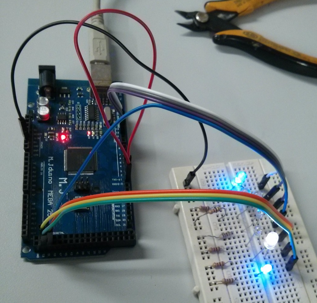
To see all that working, I had to place all LEDs in a protoboard, but don't forget to check Arduino's pin mapping to connect everything. The whole PORTB will blink LEDs now. The connection is as follows:

LED number Pin Name Mapped Pin Function
0
PB0
Digital 53
Co routine
1
PB1
Digital 52
Co routine
2
PB2
Digital 51
Co routine
3
PB3
Digital 50
Demo Blinky
4
PB4
Digital 10
Com Test - TX
5
PB5
Digital 11
Com Test - RX
6
PB6
Digital 12
Erro Check
7
PB7
Digital 13
(on board LED)
Assert Called


The project was uploaded to GitHub.

Tuesday, August 9, 2016

FreeRTOS 9.0.0 on ArduinoMEGA - Demo Blinky

By now, we have a <seemingly> operating FreeRTOS running in our ArduinoMEGA, but we're not using its whole capability. In order to test more functions, let's add a few functionalities step by step until we reach the Full Demo.

To quick start, grab the source code in https://github.com/brunolalb/FreeRTOS_ArduinoMEGA-Demo_Blinky.

FreeRTOS Demo Blinky

Yet another blinky project. This time I'm using the functionality we've studied a few months ago: here and here. This blinky project makes use of a Queue and has two tasks instead of one. One task (prvQueueSendTask()) is a sender and will add a constant value to a queue every 200 ms, while the other task (prvQueueReceiveTask()) is the receiver and will try to get the value from the queue (blocking operation) and, if the value is right, will toggle a LED on PORTB.PB6 (the same from the Blink project).

Another test performed in this project is the implementation of the configASSERT() function, which is very useful for debugging purposes. In this project, a parameter is passed to the tasks when they're created and the task should check it in order to attest that it's right. The configASSERT() will turn on the LED embedded in ArduinoMEGA's board (PORTB.PB7), as by now there's nothing much implemented yet. In the future, it could be changed to a message sent through the Serial port.

To get things moving faster, I thought on using the whole main_blinky.c from the Win32 Demo with as little changes as possible. The problem is that it wouldn't be very efficient, once the Windows Demo uses several long variables (32 bits wide) and we're running on an 8-bits microcontroller. Thus I made a few changes to optimize the code.

The main() function initializes not only the queue, which now stores unsigned char variables, but also the LEDs, using the same function as the Blink project. It then creates both tasks with predefined parameters (changed to accommodate one unsigned int) and starts the scheduler.

int main( void )
{
 /* Create the queue. */
 xQueue = xQueueCreate( mainQUEUE_LENGTH, sizeof( unsigned char ) );

 /* Setup the LED's for output. */
 vParTestInitialise();
 if( xQueue != NULL )
 {
  /* Start the two tasks as described in the comments at the top of this file. */
  xTaskCreate( prvQueueReceiveTask,   /* The function that implements the task. */
        "RX",      /* The text name assigned to the task - for debug only as it is not used by the kernel. */
        configMINIMAL_STACK_SIZE,    /* The size of the stack to allocate to the task. */
        ( void * ) mainQUEUE_RECEIVE_PARAMETER, /* The parameter passed to the task - just to check the functionality. */
        mainQUEUE_RECEIVE_TASK_PRIORITY,   /* The priority assigned to the task. */
        NULL );     /* The task handle is not required, so NULL is passed. */

  xTaskCreate( prvQueueSendTask, "TX", configMINIMAL_STACK_SIZE, ( void * ) mainQUEUE_SEND_PARAMETER, mainQUEUE_SEND_TASK_PRIORITY, NULL );
 }

 /* In this port, to use preemptive scheduler define configUSE_PREEMPTION
 as 1 in portmacro.h.  To use the cooperative scheduler define
 configUSE_PREEMPTION as 0. */
 vTaskStartScheduler();

 return 0;
}

The receiver task now blinks a LED instead of printing something. The request from the queue blocks the task for a long time while waiting something to be added to it.

static void prvQueueReceiveTask( void *pvParameters )
{
unsigned char ucReceivedValue;

 /* Remove compiler warning in the case that configASSERT() is not
 defined. */
 ( void ) pvParameters;

 /* Check the task parameter is as expected. */
 configASSERT( ( ( unsigned int ) pvParameters ) == mainQUEUE_RECEIVE_PARAMETER );

 for( ;; )
 {
  /* Wait until something arrives in the queue - this task will block
  indefinitely provided INCLUDE_vTaskSuspend is set to 1 in
  FreeRTOSConfig.h. */
  xQueueReceive( xQueue, &ucReceivedValue, portMAX_DELAY );

  /*  To get here something must have been received from the queue, but
  is it the expected value?  If it is, toggle the LED. */
  if( ucReceivedValue == 100UL )
  {
   /* The Windows Blinky Demo prints a message with printf().
    * In Arduino, we'll just blink a LED */
   vParTestToggleLED(mainLEDBLINK_TASK_LED);

   ucReceivedValue = 0U;
  }
 }
}

The sender task gave a bit more trouble, even though the changes in its code were minimal (this is why I'm not pasting it here). Its objective is to add a certain value to the queue, then sleep for a certain amount of time (200 ms). Instead of using the vTaskDelay(), as used in our last project, it uses the vTaskDelayUntil() (it is used to ensure the routine will run every X milliseconds, despite the execution time), and the time was previously defined in milliseconds. To calculate the number of ticks to wait, the pdMS_TO_TICKS() macro is used. If you expand the macro (you can check in FreeRTOS/Source/Include/projdefs.h), you'll see that it multiplies the time, in milliseconds, with the tick rate in Hz, casting everything to TickType_t, which, in Windows is an uint32_t (thus 32-bits), but in our port is an uint16_t (thus 16-bits). This means it will multiply 200 (ms) with 1000 (Hz), which exceeds 16-bits. In order to the macro to work, it has to be redefined in FreeRTOSConfig.h (if you check the comments in projdefs.h, it's already something expected). This is what was added to the end of the header:

/* It is a good idea to define configASSERT() while developing.  configASSERT()
uses the same semantics as the standard C assert() macro. */
extern void vAssertCalled( unsigned long ulLine, const char * const pcFileName );
#define configASSERT( x ) if( ( x ) == 0 ) vAssertCalled( __LINE__, __FILE__ )

/* Due to problems with integer overflow, this macro is defined here */
#define pdMS_TO_TICKS( xTimeInMs ) ( ( TickType_t ) ( ( ( unsigned long ) ( xTimeInMs ) * ( unsigned long ) configTICK_RATE_HZ ) / ( unsigned long ) 1000 ) )

As you can see, I casted this multiplication operation to an unsigned long, which is 4 bytes wide.

The vAssertCalled(), which is defined in main.c only sets the LED.

void vAssertCalled( unsigned long ulLine, const char * const pcFileName )
{
 /* Parameters are not used. */
 ( void ) ulLine;
 ( void ) pcFileName;

 vParTestSetLED(mainASSERTCALLED_LED, pdTRUE);
}

The project was uploaded to GitHub.

Friday, August 5, 2016

FreeRTOS 9.0.0 on ArduinoMEGA - Blink project

For a quick start, refer to the project on github:
http://github.com/brunolalb/FreeRTOS_ArduinoMEGA-Blink

FreeRTOS 8.2.3 to 9.0.0 changelog

It's finally time to start working on the FreeRTOS port to ArduinoMEGA. It's been a long time since I started this blog that even a new version of FreeRTOS came up. The system is now on 9.0.0 version, so that's the one I'll use from now on. So first of all, you should download the source code from their website: click here. There aren't many differences from the latest version and the code is pretty much compatible. The complete changelog can be checked here, but I'll describe some of the new features, enhancements and new ports implemented.

  • Support to completely statically allocated systems: remember the post about the memory allocation systems? heap_1.c, heap_2.c, etc? Those were about dynamic allocation. The new version supports static allocation, which means the RAM footprint is defined by linking time, rather than running time. More info can be found here and here.
  • Forcing a task to leave the blocked state: while the task is waiting for something (a semaphore take with timeout or a simple delay), the task is remained in blocked state. The new version implements an API function that unblocks a task (xTaskAbortDelay()). More info here.
  • Deleting tasks: in prior versions, when a task was deleted, its memory were only freed by the Idle function, independently of who has deleted it. Now, when one task is deleted by another task, the memory (stack and TCB) is freed immediately.
  • Obtaining a Task Handle from the Task Name: it's now possible to do this with the new API function: xTaskGetHandle(). More info here.
  • configAPPLICATION_ALLOCATED_HEAP: it's now possible to specify the memory position where the heap will be allocated when using heap_1 or heap_2 (and heap_4, but that was already possible) by declaring the array "uint8_t ucHeap[ configTOTAL_HEAP_SIZE ];". More info here.

Creating required files and the Eclipse project

The initial objective will be to have the bare minimal amount of code to run the FreeRTOS and just make a LED blink. On your file explorer, create the folder where your project will be. In that folder, create another folder called FreeRTOS, where we'll keep all the RTOS code, just for cleanliness purposes. Let's copy the source files from the FreeRTOS official folder:
  • The basic kernel: Source/tasks.c, queue.c and list.c
  • Memory management: Source/MemMang/heap_1.c (this is the simpler one)
  • The portable bits: Source/portable/[compiler]/[processor]/port.c and portmacro.c
    • In this case, I created the folder WinAVR as the [compiler] and ATmega2560 as the [processor].
    • I copied the files from the ATmega323 port (FreeRTOSv9.0.0\FreeRTOS\Source\portable\GCC\ATMega323) to start with something close to what I want.
  • Header files: Source/include/ (you may copy the whole folders) and Demo\Common\include\partest.h.
To the root folder of the project we'll add the application specifics (I copied them from the ATmega323 Demo project, in FreeRTOSv9.0.0\FreeRTOS\Demo\AVR_ATMega323_WinAVR):
  • FreeRTOSConfig.h 
  • main.c
  • ParTest/ParTest.c
This is what we have in our project folder:


Supposing that you already have your Eclipse configured (if not, check here), open it and go to File > New > C++ Project.
  1. Choose the Empty Project under the folder "AVR Cross Target Application"
  2. Pick a name (FreeRTOS_ArduinoMEGA - rev0.1) and point the location to your project folder


  3. Click Next
  4. Click Next again (Debug and Release configs)
  5. Choose the MCU (ATmega2560) and Frequency (16000000 - that's 16 followed by 6 zeroes, 16MHz)
  6. Click Finish. This is what your Project Explorer should be showing:


  7. In the Project Properties, under AVR > AVRDude, in the box Programmer Configuration, choose the config you created for the Blink project (or follow the steps 9 and 10 here): ArduinoMEGA2560 - STK500v2.
  8. Still on the Project Properties, go to C/C++ Build > Settings. On the tab Tool Settings:
    1. Additional Tools in Toolchain, check "Generate HEX file for Flash memory"
    2. AVR Compiler > Optimization, Optimization Levels: Size Optimization (-Os), uncheck Pack Structs and Short Enums
    3. AVR Compiler > Language Standard, uncheck "char is unsigned" and "bitfields are unsigned"
    4. Do the same to AVR C++ Compiler
  9. Adjusting some paths under C/C++ General > Paths and Symbols > Includes, add the following workspace directories:
    1. Project's root
    2. FreeRTOS/Demo/Common/include
    3. FreeRTOS/Source/include
    4. FreeRTOS/Source/portable/WinAVR/ATmega2560
By now, the project should be ready, but the code is all wrong, so let's work on that.

Working on port.c and portmacro.h

Before we start, we should define a few things. First of all, the main timer for the FreeRTOS (the one that will provide the Tick) will be Timer 1 and the Tick will be 1 ms (1000 Hz). No special reason, as it could be any other, but two things made me choose this: it's the same used in AVR323 and it's the same time we used on the Blink project.
This timer should produce interrupts every 1 ms, without any interference of the FreeRTOS functions, thus a simple timer that counts to a certain value, indicates an interrupt and resets on its own, restarting the process. Refer to the function prvSetupTimerInterrupt( void) around line 402 of the port.c file. There are a few differences, since the ATmega323 is bit simpler.
/*
 * Setup timer 1 compare match A to generate a tick interrupt.
 */
static void prvSetupTimerInterrupt( void )
{
uint32_t ulCompareMatch;
uint8_t ucHighByte, ucLowByte;

 /* Using 16bit timer 1 to generate the tick.  Correct fuses must be
 selected for the configCPU_CLOCK_HZ clock. */

 ulCompareMatch = configCPU_CLOCK_HZ / configTICK_RATE_HZ;

 /* We only have 16 bits so have to scale to get our required tick rate. */
 ulCompareMatch /= portCLOCK_PRESCALER;

 /* Adjust for correct value. */
 ulCompareMatch -= ( uint32_t ) 1;

 /* Setup compare match value for compare match A.  Interrupts are disabled 
 before this is called so we need not worry here. */
 ucLowByte = ( uint8_t ) ( ulCompareMatch & ( uint32_t ) 0xff );
 ulCompareMatch >>= 8;
 ucHighByte = ( uint8_t ) ( ulCompareMatch & ( uint32_t ) 0xff );
 OCR1AH = ucHighByte;
 OCR1AL = ucLowByte;

 /* Setup clock source and compare match behaviour. */
 ucLowByte = portCLEAR_COUNTER_ON_MATCH_TCCR1A;
 TCCR1A = ucLowByte;
 ucLowByte = portCLEAR_COUNTER_ON_MATCH_TCCR1B | portPRESCALE_64;
 TCCR1B = ucLowByte;

 /* Enable the interrupt - this is okay as interrupt are currently globally
 disabled. */
 ucLowByte = TIMSK1;
 ucLowByte |= portCOMPARE_MATCH_A_INTERRUPT_ENABLE;
 TIMSK1 = ucLowByte;
}
/*-----------------------------------------------------------*/
You probably realize two changes: The addition of the TCCR1A config and the correct config of the TIMSK1 register (was TIMSK on ATmega323). The definitions (around line 90) change to the following.
/* Hardware constants for timer 1. */
#define portCLEAR_COUNTER_ON_MATCH_TCCR1A  ( ( uint8_t ) 0b00000000 )
#define portCLEAR_COUNTER_ON_MATCH_TCCR1B  ( ( uint8_t ) 0b00001000 )
#define portPRESCALE_64     ( ( uint8_t ) 0b00000011 )
#define portCLOCK_PRESCALER    ( ( uint32_t ) 64 )
#define portCOMPARE_MATCH_A_INTERRUPT_ENABLE  ( ( uint8_t ) 0b00000010 )

Even though both microcontrollers use the same AVR architecture, the ATmega2560 has 2 more registers to be saved: RAMPZ and EIND, thus the functions portSAVE_CONTEXT() and portRESTORE_CONTEXT() will need a tweek.

#define portSAVE_CONTEXT()     \
 asm volatile ( "push r0   \n\t" \
   "in r0, __SREG__  \n\t" \
   "cli    \n\t" \
   "push r0   \n\t" \
   "in r0, 0x3b  \n\t" \
   "push r0   \n\t" \
   "in r0, 0x3c  \n\t" \
   "push r0   \n\t" \
   "push r1   \n\t" \
   "clr r1   \n\t" \
   "push r2   \n\t" \
   "push r3   \n\t" \
   "push r4   \n\t" \
   "push r5   \n\t" \
   "push r6   \n\t" \
   "push r7   \n\t" \
   "push r8   \n\t" \
   "push r9   \n\t" \
   "push r10   \n\t" \
   "push r11   \n\t" \
   "push r12   \n\t" \
   "push r13   \n\t" \
   "push r14   \n\t" \
   "push r15   \n\t" \
   "push r16   \n\t" \
   "push r17   \n\t" \
   "push r18   \n\t" \
   "push r19   \n\t" \
   "push r20   \n\t" \
   "push r21   \n\t" \
   "push r22   \n\t" \
   "push r23   \n\t" \
   "push r24   \n\t" \
   "push r25   \n\t" \
   "push r26   \n\t" \
   "push r27   \n\t" \
   "push r28   \n\t" \
   "push r29   \n\t" \
   "push r30   \n\t" \
   "push r31   \n\t" \
   "lds r26, pxCurrentTCB \n\t" \
   "lds r27, pxCurrentTCB + 1 \n\t" \
   "in r0, 0x3d  \n\t" \
   "st x+, r0   \n\t" \
   "in r0, 0x3e  \n\t" \
   "st x+, r0   \n\t" \
 );
#define portRESTORE_CONTEXT()     \
 asm volatile ( "lds r26, pxCurrentTCB \n\t" \
   "lds r27, pxCurrentTCB + 1 \n\t" \
   "ld r28, x+   \n\t" \
   "out __SP_L__, r28  \n\t" \
   "ld r29, x+   \n\t" \
   "out __SP_H__, r29  \n\t" \
   "pop r31   \n\t" \
   "pop r30   \n\t" \
   "pop r29   \n\t" \
   "pop r28   \n\t" \
   "pop r27   \n\t" \
   "pop r26   \n\t" \
   "pop r25   \n\t" \
   "pop r24   \n\t" \
   "pop r23   \n\t" \
   "pop r22   \n\t" \
   "pop r21   \n\t" \
   "pop r20   \n\t" \
   "pop r19   \n\t" \
   "pop r18   \n\t" \
   "pop r17   \n\t" \
   "pop r16   \n\t" \
   "pop r15   \n\t" \
   "pop r14   \n\t" \
   "pop r13   \n\t" \
   "pop r12   \n\t" \
   "pop r11   \n\t" \
   "pop r10   \n\t" \
   "pop r9   \n\t" \
   "pop r8   \n\t" \
   "pop r7   \n\t" \
   "pop r6   \n\t" \
   "pop r5   \n\t" \
   "pop r4   \n\t" \
   "pop r3   \n\t" \
   "pop r2   \n\t" \
   "pop r1   \n\t" \
   "pop r0   \n\t" \
   "out 0x3c, r0  \n\t" \
   "pop r0   \n\t" \
   "out 0x3b, r0  \n\t" \
   "pop r0   \n\t" \
   "out __SREG__, r0  \n\t" \
   "pop r0   \n\t" \
 );

The same goes to the pxPortInitialiseStack(). After saving the address for the task, you'll need an extra increment of the stack pointer, and after saving the interrupt enable, you'll need to save the initialize value of both RAMPZ and EIND registers (they'll be initialized with 0). Then, you can save the rest of the registers. I'll copy here only part of the function.

 /* The start of the task code will be popped off the stack last, so place
 it on first. */
 usAddress = ( unsigned portSHORT ) pxCode;
 *pxTopOfStack = ( StackType_t ) ( usAddress & ( unsigned portSHORT ) 0x00ff );
 pxTopOfStack--;

 usAddress >>= 8;
 *pxTopOfStack = ( StackType_t ) ( usAddress & ( unsigned portSHORT ) 0x00ff );
 pxTopOfStack--;

 *pxTopOfStack = 0;
 pxTopOfStack--;

 /* Next simulate the stack as if after a call to portSAVE_CONTEXT().  
 portSAVE_CONTEXT places the flags on the stack immediately after r0
 to ensure the interrupts get disabled as soon as possible, and so ensuring
 the stack use is minimal should a context switch interrupt occur. */
 *pxTopOfStack = ( StackType_t ) 0x00; /* R0 */
 pxTopOfStack--;
 *pxTopOfStack = portFLAGS_INT_ENABLED;
 pxTopOfStack--;

 /* If we have an ATmega2560, we are also saving the RAMPZ and EIND registers.
  * We should default those to 0.
  */
 *pxTopOfStack = ( portSTACK_TYPE ) 0x00; /* EIND */
 pxTopOfStack--;
 *pxTopOfStack = ( portSTACK_TYPE ) 0x00; /* RAMPZ */
 pxTopOfStack--;


 /* Now the remaining registers.   The compiler expects R1 to be 0. */
 *pxTopOfStack = ( StackType_t ) 0x00; /* R1 */
 pxTopOfStack--;

The port.c is done.

As for the header (portmacro.h), there is no need to change anything (that's the cool thing of starting from a similar architecture).

FreeRTOSConfig.h

This file won't need much work. First of all, our Arduino is running at 16 MHz, thus the configCPU_CLOCK_HZ has to be changed. The tick rate remains at 1000 Hz. The ATmega2560 has 8KB of SRAM, instead of the 2KB available in the ATmega323, thus change the configTOTAL_HEAP_SIZE to something closer to 8KB (I used 7500). I'm not using the idle hook, thus set configUSE_IDLE_HOOK to 0.

main.c

This will need some extra work, as by now we're only trying to blink a led, so most of it is going away. This is what I'm left with.

#include <stdlib.h>
#include <string.h>

/* Scheduler include files. */
#include "FreeRTOS.h"
#include "task.h"

/* Demo file headers. */
#include "partest.h"

/* Priority definitions for most of the tasks in the demo application.  Some
tasks just use the idle priority. */
#define mainLED_TASK_PRIORITY   ( tskIDLE_PRIORITY + 1 )

/* The sleeping period for blinking the LED */
#define mainLEDBLINK_TASK_PERIOD  ( ( TickType_t ) 1000 / portTICK_PERIOD_MS  )

/* LED that is toggled every mainLEDBLINK_TASK_PERIOD */
#define mainLEDBLINK_TASK_LED   ( 6 )

/*
 * The task function for the "Blink" task.
 */
static void vBlink( void *pvParameters );

/*-----------------------------------------------------------*/

int main( void )
{
 /* Setup the LED's for output. */
 vParTestInitialise();

 /* Create the tasks defined within this file. */
 xTaskCreate( vBlink, "Blink", configMINIMAL_STACK_SIZE, NULL, mainLED_TASK_PRIORITY, NULL );

 /* In this port, to use preemptive scheduler define configUSE_PREEMPTION
 as 1 in portmacro.h.  To use the cooperative scheduler define
 configUSE_PREEMPTION as 0. */
 vTaskStartScheduler();

 return 0;
}
/*-----------------------------------------------------------*/

static void vBlink( void *pvParameters )
{
 /* The parameters are not used. */
 ( void ) pvParameters;

 /* Cycle forever, toggling the LED and sleeping */
 while(1)
 {
  vParTestToggleLED(mainLEDBLINK_TASK_LED);
  vTaskDelay(mainLEDBLINK_TASK_PERIOD);
 }

}
/*-----------------------------------------------------------*/

I know ArduinoMEGA's LED is connected to the 7th bit of PORTB, but I added an extra on the 6th bit (digital port 12 on the board) for debug purposes.

ParTest.c

The last changes are in ParTest.c, as the original used the whole port as LEDs. I'm using only bits 6 and 7. Also, the ATmega2560 has this register PINB that, when you write a 1 to a bit, it toggles the value of the output.

#include "FreeRTOS.h"
#include "task.h"
#include "partest.h"

/*-----------------------------------------------------------
 * Simple parallel port IO routines.
 *-----------------------------------------------------------*/

#define partstLEDS_OUTPUT ( ( unsigned char ) 0b11000000 )
#define partstALL_OUTPUTS_OFF ( ( unsigned char ) 0b00111111 )
#define partstMAX_OUTPUT_LED ( ( unsigned char ) 7 )
#define partstMIN_OUTPUT_LED ( ( unsigned char ) 6 )

static volatile unsigned char ucCurrentOutputValue = partstALL_OUTPUTS_OFF;

/*-----------------------------------------------------------*/

void vParTestInitialise( void )
{
 ucCurrentOutputValue = partstALL_OUTPUTS_OFF;

 /* Set port B direction to outputs.  Start with all output off. */
 DDRB = partstLEDS_OUTPUT;
 PORTB &= ucCurrentOutputValue;
}
/*-----------------------------------------------------------*/

void vParTestSetLED( unsigned portBASE_TYPE uxLED, signed portBASE_TYPE xValue )
{
unsigned char ucBit = ( unsigned char ) 1;

 if(( uxLED <= partstMAX_OUTPUT_LED ) && ( uxLED >= partstMIN_OUTPUT_LED ))
 {
  ucBit <<= uxLED; 

  vTaskSuspendAll();
  {
   if( xValue == pdFALSE )
   {
    ucBit ^= ( unsigned char ) 0xff;
    ucCurrentOutputValue &= ucBit;
    PORTB &= ucCurrentOutputValue;
   }
   else
   {
    ucCurrentOutputValue |= ucBit;
    PORTB |= ucCurrentOutputValue;
   }
  }
  xTaskResumeAll();
 }
}
/*-----------------------------------------------------------*/

void vParTestToggleLED( unsigned portBASE_TYPE uxLED )
{
 unsigned char ucBit;

 if(( uxLED <= partstMAX_OUTPUT_LED ) && ( uxLED >= partstMIN_OUTPUT_LED ))
 {
  ucBit = ( ( unsigned char ) 1 ) << uxLED;

  vTaskSuspendAll();
  {

   PINB = ucBit;
   ucCurrentOutputValue = PORTB;
  }
  xTaskResumeAll();   
 }
}

I guess this is it!
Compile, add the forgotten ; and send it to your Arduino. Try changing the delay on the Blink task and send it again. I uploaded the whole project to GitHub.

Monday, August 1, 2016

ArduinoMEGA on Eclipse without Arduino SDK

More than being quite limited, the Arduino IDE comes with its own SDK, which means we can't have our own main() function. I chose Eclipse because it's free and easy to use and there are a few tutorials around on how to use an Arduino board with Eclipse IDE. So, I read lots of them and came up with my own step by step:

  1. On Windows:
    1. Download and install Eclipse IDE for C/C++ Developers (today, the latest is Mars 2)
    2. Download and install WinAVR (today, the latest is 20100110)
    3. Open Eclipse, go to Help > Install New Software.... Add the following to the "Work with" section: http://avr-eclipse.sourceforge.net/updatesite and install the plugin.
    4. Done!
  2. On Linux (Ubuntu in my case):
    1. Install Eclipse
      1. sudo apt-get install eclipse
    2. Install AVR compiler
      1. sudo apt-get install avrdude binutils-avr gcc-avr avr-libc gdb-avr
    3. Open Eclipse, go to Help > Install New Software.... Add the following to the "Work with" section: http://avr-eclipse.sourceforge.net/updatesite and install the plugin.
    4. Add your user to the dialout group, then logout and login again (this is in order to your user have permission to access the serial port).
      1. sudo usermod -a -G dialout <username>
    5. Done!


Wait, what? This is it? Yep! Unless you didn't install WinAVR on its default location (C:/WinAVR-20100110). In that case, you'll need to adjust the paths in the AVR Eclipse plugin (on Eclipse, go to Window > Preference > AVR > Paths):
  • AVR-GCC: <WinAVR path>\bin
  • GNU make: <WinAVR path>\utils\bin
  • AVR Header Files: <WinAVR path>\avr\include
  • AVRDude: <WinAVR path>\bin

Yes, this screen is from Ubuntu.

Now let's create a first project just to check whether it works. Can you guess? A Blink project! This time, we won't use any of the easy Arduino stuff. Instead, let's open the microcontroller datasheet and start configuring the registers. In Eclipse, go to File > New > C++ Project (in Linux, you'll go to File > New > Project and choose C++ Project under C/C++ Folder).
  1. Choose the Empty Project under the folder "AVR Cross Target Application"


  2. Pick a name (Blink) and a location
  3. Click Next
  4. Click Next again
  5. Choose the MCU (ATmega2560) and Frequency (16000000 - that's 16 followed by 6 zeroes, 16MHz)
  6. Click Finish
  7. Go to the project properties (click with the left button on the project and go to Properties)
  8. Under AVR > Target Hardware you can check if the MCU and frequency were correctly chosen

  9. Under AVR > AVRDude, in the box Programmer Configuration, click New....
  10. Choose the bootloader version (Atmel STK500 Version 2.x firmware), choose a name for the configuration, choose the correct COM port in "Override default port" (use the Device Manager in Windows -i.e. COM18 -, or, in Linux, the command line "dmesg | grep tty" and remember to put "/dev/" before the port name - i.e. /dev/ttyUSB0), and override default baudrate with 115200  and click OK.
  11. Still on the Project Properties, go to C/C++ Build > Settings. On the tab Tool Settings:
    1. Additional Tools in Toolchain, check "Generate HEX file for Flash memory"
    2. AVR Compiler > Optimization, Optimization Levels: Size Optimization (-Os), uncheck Pack Structs and Short Enums
    3. AVR Compiler > Language Standard, uncheck "char is unsigned" and "bitfields are unsigned"
    4. Do the same to AVR C++ Compiler
  12. Now for the source code files, click with the left button on the project folder (in Project Explorer) and go to New > Folder, choose the project and the name ("src") and click Finish. Again in the Project Explorer, left click on new folder and New > Source File, choose the name ("blink.cpp") and Finish.
  13. Copy the following source code to your file.
    #include <avr/io.h>
    #include <avr/interrupt.h>
    
    int main(void)
    {
     //Setup the clock (timer 1, 62.5kHz (16MHz / 256 = 62.5kHz), CTC mode, interrupt on)
     cli(); //Disable global interrupts
     TCCR1A = 0b00000000; //no physical outputs (COM1Ax, COM1Bx and COM1Cx == 0b00), WGM10 and WGM11 = 0.
     TCCR1B = 0b00001000; //input capture off, WGM13 = 0, WGM12 = 1, prescaler 1/256 (CS1x = 0b100 - off by now, thus 0b000)
     TCCR1C = 0b00000000; //writing a 1 to any of the 3 most significative bits forces a compare match
     TCNT1 = 0x0000; //resets the timer counter
     OCR1A = 62499; //Count 62500 cycles for 1 second interrupt
     OCR1B = 0x0000; //output compare register B is not used
     OCR1C = 0x0000; //output compare register C is not used
     ICR1 = 0x0000; //input capture not used
     TIMSK1 = 0b00000010; //input capture interrupt off, output compare B and C interrupts off, output compare A interrupt on, overflow interrupt off
     TIFR1 = 0x00; //resets the interrupt flags
     TCCR1B |= 0b00000100; //turn on the timer (CS1x = 0b100)
     sei(); //Enable global interrupts
    
     //Setup the I/O for the LED (digital pin 13, or PB7, according to the Arduino pin mapping)
     DDRB = 0b10000000; //PB7 is digital pin 13 (LED), configured as an output
     PORTB |= 0b10000000; //Set PB7 high to turn on LED
    
     while(1) { } //Loop forever, interrupts do the rest
    }
    
    ISR(TIMER1_COMPA_vect) //Interrupt Service Routine - flag is cleared automatically
    {
      PORTB ^= (1<<PB7); //Use xor to toggle the LED
    }
  14. Build it (Ctrl+B)
    1. Edit: If you're using Windows 10 (or other versions) and encountered this error: make: *** [src/blink.o] Error -1073741502, follow the steps on this post.
  15. To transfer to the board, there's a little catch (in Windows): seems like Arduino IDE uses a modified version of AVRDude that resets the board before attempting to upload the HEX file (this is needed in order to the Arduino enter the bootloader). So, if you get this timeout message, just hold the reset button on your board and release when you click the Upload button (that's the AVR button with an arrow pointing downwards, or CTRL+ALT+U).
    avrdude: stk500_2_Receive_Message(): timeout
  16. Now modify the OCR1A to 6249, compile and upload again: The timer will run 10 times faster, thus the LED must blink faster, if it doesn't, well...find out what's wrong and tell me in the comments box :)

Right now you should have a working hardware, with a working IDE and burner (close enough).
The project is available on GitHub.

On the next post, let's talk business and start porting the FreeRTOS.